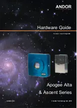
Apogee Alta
& Ascent Series
andor.com
©
Andor Technology Ltd. 2016
Hardware Guide
Version 1.5 rev 23 Sep 2016
Страница 1: ...Apogee Alta Ascent Series andor com Andor Technology Ltd 2016 Hardware Guide Version 1 5 rev 23 Sep 2016 ...
Страница 2: ...3 2 Replacement Items 11 2 3 3 Optional Items 12 2 4 Product Description 13 2 4 1 Ascent Series 13 2 4 2 Alta F Series 14 2 5 Power and Signal Connections 15 SECTION 3 INSTALLING YOUR CAMERA SOFTWARE 17 3 1 Install Update Apogee Camera Driver 17 3 1 1 Installation Example For Windows 7 17 3 2 Install MaxIm DL 18 3 3 Uninstalling Apogee Software 18 SECTION 4 SETTING UP MAXIM DL SOFTWARE TO CONTROL ...
Страница 3: ... Specifications 35 8 3 Mechanical Drawings Ascent 36 8 4 Mechanical Drawings Alta 37 D01 37 D02 38 D07 39 SECTION 9 APOGEE FILTER WHEEL INSTALLATION 40 9 1 Introduction and Setup 40 9 2 Update Apogee Driver Apogee DLL 40 9 3 Driver Installation procedure shown for Windows 7 41 9 4 Install MaxIm DL 42 9 5 Using MaxIm DL 42 9 6 Filter Wheel Installation 44 9 6 1 Installing Filters 44 9 6 2 Mounting ...
Страница 4: ...o cover connection of power and signal cables Section 5 2 1 3 27 Oct 2015 Updated mechanical drawings Removed Alta D10 Deep cooled drawing not available as standard product 1 4 19 Aug 2016 General updates throughout all sections Removed references to Windows XP and Vista Updated maximum exposure to 95 minutes Corrected issue were images in PDF showed Alt text information 1 5 26 Sep 2016 Corrected ...
Страница 5: ...power supply cord is required ensure replacement is of same type and rating 11 Ensure that the fans are not blocked and that there is sufficient clearance to enable airflow required for cooling 12 While running an experiment try to keep room temperature as stable as possible 13 Performance of the system may be adversely affected by rapidly changing environmental conditions or operation outside of ...
Страница 6: ...spillage occurs on the product switch off power immediately and wipe off with a dry lint free cloth 22 If any ingress of liquids has occurred or is suspected unplug the mains cables do not use and contact Customer Support 23 Do not expose the product to extreme hot or cold temperatures 24 Do not expose the product to open flames 25 Do not allow objects to fall on the product 26 Refer to Section 6 ...
Страница 7: ...of this equipment please contact the representative from whom your system was purchased or Europe Andor Technology Ltd 7 Millennium Way Springvale Business Park Belfast BT12 7AL Northern Ireland Tel 44 0 28 9023 7126 Fax 44 0 28 9031 0792 USA Andor Technology 425 Sullivan Avenue Suite 3 South Windsor CT 06074 USA Tel 860 290 9211 Fax 860 290 9566 Asia Pacific Andor Technology Japan Andor Technolog...
Страница 8: ...to change without notice Any changes or modifications not expressly approved in this manual could void your authority to operate this equipment If you require further information about this unit you may contact your local representative The latest contact details for your local representative may be found at our website www andor com 1 3 Trademarks and Patent Information Andor the Andor logo and S...
Страница 9: ...ing full advantage of Andor s manufacturing facilities and quality systems Apogee cameras have been used for high end astronomical applications like capturing the first images of optical counterparts of gamma ray bursts plus thousands of discoveries of comets near Earth asteroids and extra solar planets The Apogee range of cameras will always be on the brink of discovery with the latest cutting ed...
Страница 10: ...nected to the camera and plugged into the power outlet If the camera is to be connected to a moving device such as a telescope be sure to secure the cable with cable ties and allow enough slack so that the cable connector is not stressed during movement Always allow the sensor warm up slowly Do not expose the imaging sensor to direct sunlight for prolonged periods i e removing the lid assembly or ...
Страница 11: ...listed below or appears it may be damaged please contact your local sales representative 2 3 1 Standard Supplied Items Apogee Alta or Ascent Camera Apogee CD This CD contains documentation for your Apogee Camera USB Cable A standard 15 3 metre USB cable is included with the Apogee camera unit Alta 12V power supply Ascent 6V supply 2 3 2 Replacement Items 12V Alta power supply 6V Ascent power suppl...
Страница 12: ...he time of ordering or purchased at a later date from Andor Please contact us or refer to our website www andor com for further information Flange Adapters Lens Adapters Telescope Adapter USB and Fibre Optic Range extender Filter Wheels including a range of filters Note Only use accessories that are specified or supplied by Andor as performance cannot be guaranteed using other accessories ...
Страница 13: ...ies The Ascent Camera Series supports a variety of interline transfer sensors with high quantum efficiency and low dark current Refer to the product specification sheet for model specific information Figure 1 Ascent Power and Signal Connections Figure 2 Ascent view of camera window and sensor also showing Accessory Interface and Cooling Fan location Status LEDs Power Camera I O port USB Accessory ...
Страница 14: ...ariety of front illuminated back illuminated and interline transfer CCDs Refer to the product specification sheet for model specific information Figure 3 Alta Power and Signal Connections Note Shutter not shown may also be present in some models Figure 4 View of Alta Shutter and Mounting locations left and view of cooling fans right Power Status LEDs USB Camera I O port Camera Window External Shut...
Страница 15: ...tter is open or the camera is waiting for an external trigger Alternatively the LEDs can be turned off if you are concerned about stray light Camera I O Port Apogee camera systems provide an 8 pin Mini DIN connector enabling various hardware signals to be controlled by the device Five of the eight pins are programmable and of the remaining pins pin 6 is for EEPROM Write Protect Section 3 5 1 pin 8...
Страница 16: ... documentation for these properties for additional details regarding their operation The fixed function descriptions of each pin are as follows Pin 1 Trigger Input Used to initiate triggered exposures both single exposures and sequences or TDI row read operations When the CameraMode property is set to Apn_CameraMode_ExternalTrigger the ICamera2 interface object will automatically enable this pin t...
Страница 17: ...r camera to a PC before installing the drivers If you do and the Add New Hardware Wizard appears please select the Cancel button 1 Make sure your Windows user account has administrator privileges 2 Double click on the setupApogeeSoftware 3 If you see the following error dialog then please refer to section 3 3 After removing v3 software try executing the setupApogeeSoftware exe again 4 Follow the i...
Страница 18: ...ommend you install it prior to setting up your Apogee camera Please see the MaxIm DL documentation for specific instructions related to installation of this software Apogee cameras are supported by MaxIm DL version 3 21 and beyond MaxIm DL and other 32 bit applications require the 32 bit installer For other software please refer to the accompanying installation and user documentation 3 3 Uninstall...
Страница 19: ... in this section contains specific MaxIm DL screenshots These screenshots were correct and accurate as of MaxIm v5 06 the current shipping version at the time of writing this document It is possible that users with other versions of MaxIm DL may notice slight layout changes from what is described here Refer to the Maxim DL User guide for further information Remember to register your software so th...
Страница 20: ...cation of the camera For cameras with a network interface select Ethernet enter the IP address of the camera and set Device Number to its TCP port number If the camera is selected as USB only the Device Number control is available set it to the camera identifying number as enumerated by the operating system 6 While the camera is connected the Interface controls are not available they are replaced ...
Страница 21: ...his is appropriate if the image is moving smoothly across the CCD sensor In Kinetics mode the sensor must be masked so that a specified number of full width but reduced height images known as sections can be rapidly acquired on a single CCD frame Readout occurs only after all requested sections have been imaged For further information consult the documentation for your camera 13 For cameras with f...
Страница 22: ... camera is Active during Flushing to remove charge from the array at Wait Trigger to show when the camera is waiting for a trigger when an Ext Trigger is received Ext Shutter to show the state of the external shutter Ext Readout to show the state of the external readout trigger and when the camera has stabilized At Temperature 19 The Shrink button toggles between the full size dialog box and just ...
Страница 23: ... may be fine tuned to accelerate readout please contact us for more information 24 Use the Kinetics Parameters to specify the Section Height in pixels and the Number of Sections these values will be determined by how your CCD chip is masked Set the Rate to the time interval in seconds per section Note that the timing implied by these controls takes precedence over the exposure time specified elsew...
Страница 24: ... Ascent can be connected to a telescope lens or other equipment using a wide range of plate lens adapters and other accessories The general steps are outlined below 1 Ensure the camera control software and drivers have been installed 2 Line up the appropriate camera mounting adapter for your application to the camera face plate mounting holes 3 Insert the supplied mounting screws and lightly tight...
Страница 25: ...sconnection from the mains power supply is required 5 2 1 Apogee Alta 1 Connect the supplied USB cable between the USB connector on the camera and the corresponding slot on the PC 2 Insert the 12V DC power cable into the power connector on the connections panel of the camera 3 Connect the power cable for the PSU to the mains supply 4 Turn ON the PC 5 Start your software 6 Start acquiring data Alta...
Страница 26: ...r on the camera and the corresponding slot on the PC 6 Insert the 12V DC power cable into the power connector on the Connections panel of the camera 7 Connect the power cable for the PSU to the mains supply 8 Turn ON the PC 9 Start your software 10 Start acquiring data Ascent Camera Ascent Camera PC 6 V DC PSU USB Power Cable To Mains Power Supply ...
Страница 27: ...airflow become blocked the thermoelectric cooler may run a few degrees warmer than normal and the camera body could overheat causing damage to some of the more sensitive components 6 2 Cleaning the Camera Window At some point it may become necessary to clean debris from the CCD imaging sensor window Cleaning the camera window can provide effective results providing you carefully follow these step ...
Страница 28: ...face 2 Use the camera control software to open the shutter TIP If your program does not have this feature try starting a long exposure Over exposing the CCD to room light will not damage the CCD 3 Customers using Maxim DL may select the Setup tab and click Connect 4 Once connected to the camera select the Settings tab and click the Options arrow 5 A new window will appear click Open Shutter The sh...
Страница 29: ...ff Allow it to fully dry before proceeding Always orient the compressed air can in an upright position before spaying It is recommended to use an air can a compressor system may spray droplets of oil 6 With the shutter open turn the camera on its side making it easier for particles to fall out of the camera head You might have to remove a button head screw from the tripod mount for the camera to s...
Страница 30: ...particles stuck on the window use an optics brush to dislodge them from the window surface Spray the dust particles out of the camera head with compressed air 9 Make sure to use compressed air to clean your adapter tubes and focal reducers so you don t get more dust once everything s assembled ...
Страница 31: ...r of electrons is exactly proportional to number of photons captured by each pixel for its portion of the sky In practice the number of electrons is equal to the number that were freed by photons from the sky impacting on the pixel and by the pixel s thermal agitation or dark current Furthermore even before the exposure starts each pixel value is usually biased higher than zero by some amount The ...
Страница 32: ...ield image is to record the pixel to pixel variation in the sensitivity of the imaging system Once the raw image of the sky is corrected for dark current and bias a flat field correction can be done The flat field image may also need a dark correction if it required a long exposure but usually flat field images do not need this adjustment Flat field images should be produced before or after each i...
Страница 33: ... capture faint extended subjects like nebulae and galaxies faster than longer focal ratio instruments Incredibly a camera with a typical 200mm lens and an f ratio of 2 3 will capture more of the Andromeda galaxy than the 200 inch Hale Telescope operating at f3 3 during the same exposure time However even though a modest 200mm lens out speeds one of the world s most famous telescopes the scale of t...
Страница 34: ...tive humidity 70 non condensing Power 20W maximum power with maximum cooling AC DC brick supply with int l AC input plug 100 240V 50 60Hz Alternate 6V input from user s source Overvoltage Category CAT II An overvoltage category of CAT II means that the equipment is designed to cope with transient voltages above the rated supply that would be experienced by any product connected to a mains socket i...
Страница 35: ...imum cooling AC DC brick supply with int l AC input plug 100 240V 50 60Hz Alternate 12V input from user s source Overvoltage Category CAT II An overvoltage category of CAT II means that the equipment is designed to cope with transient voltages above the rated supply that would be experienced by any product connected to a mains socket in a building Rated Pollution Pollution Degree 2 Normally only n...
Страница 36: ...36 Version 1 5 rev 26 Sep 2016 Apogee Astronomy Alta and Ascent Manual 8 3 Mechanical Drawings Ascent Dimensions in inches ...
Страница 37: ...37 Version 1 5 rev 26 Sep 2016 Apogee Astronomy Alta and Ascent Manual 8 4 Mechanical Drawings Alta Dimensions in inches mm D01 ...
Страница 38: ...38 Version 1 5 rev 26 Sep 2016 Apogee Astronomy Alta and Ascent Manual D02 ...
Страница 39: ...39 Version 1 5 rev 26 Sep 2016 Apogee Astronomy Alta and Ascent Manual D07 ...
Страница 40: ...ers 2 Install the MaxIm DL application software 3 Connect to the Filter Wheel using MaxIm DL 4 Integrate filters into the Filter Wheel and integrate into your system 5 Begin using your new Apogee Filter Wheel 9 2 Update Apogee Driver Apogee DLL If you already have Apogee drivers installed on your system be sure to update to the latest version before proceeding The disk included with your Filter Wh...
Страница 41: ...ur Windows user account has administrator privileges Double click on the setupApogeeDriver for your operating system type 32 or 64 bit 1 Follow the installation wizard instructions and click Finish once complete 2 Upon successful driver installation connect your Filter Wheel to the PC Watch the message balloon in the lower right corner state the OS search for and successfully install the drivers f...
Страница 42: ...rovides detailed instructions for setting up the software and getting started This section covers a quick reference of how to connect to your Alta Filter Wheel using MaxIm DL The information in this section contains specific MaxIm DL screenshots These screenshots were accurate as of MaxIm v5 06 appearance of other versions may vary To begin launch the MaxIm DL camera control window Under Camera 1 ...
Страница 43: ... this feature The Model should be set to the type of Filter Wheel you are controlling Click the Advanced button and press Search to find the device Choose the Filter Wheel from the list and verify that the Connection Interface is set to USB 2 0 and click OK Press OK in the Setup Apogee USB Net window and then click Connect in the Camera Control window The Alta Filter Wheel is now setup in MaxIm DL...
Страница 44: ...e two buttonhead screws from the back of the mounting flange Set aside the mounting flange and four buttonhead screws for now 3 Flip Filter Wheel right side up and set on the edge of a table The motor should hang off the side so the housing does not rock back and forth 4 Remove the ten 6 32 x 5 16 flathead screws from the perimeter of the lid using the 5 64 Allen wrench provided 5 Remove the lid m...
Страница 45: ...ome kind of protection such as gloves or the glass packing material It is ok to rotate the carousel by hand to make it easier to install filters Some filters will be tighter than others when resting in the carousel openings do not force into place Centre filters in carousel openings use four tooth picks around the edges of each filter if needed 8 Fasten filters using the screw and nylon washer com...
Страница 46: ...40 x 3 16 Buttonhead Screw 1X 4 Nylon Washer 5mm Thick Filters 1X 4 40 x 1 4 Buttonhead Screw 1X 4 Nylon Washer 1X 4 Nylon Spacer 7mm Thick Filters 1X 4 40 x 5 16 Buttonhead Screw 1X 4 Nylon Washer 3X 4 Nylon Spacer Now that all the filters have been installed take a moment to blow out the housing in case of any dust or debris Place lid back on Filter Wheel housing making sure not to damage the li...
Страница 47: ...nt flush with adapter surface There are two hole patterns machined into the flange to accommodate different Alta camera sizes 2 Line up the Filter Wheel with the adapter flange in the configuration shown below so the two mounting holes line up with the threaded holes of the flange 3 Lightly screw in two 10 32 x 7 16 buttonhead screws and flip assembly upside down to mount the two buttonhead screws...
Страница 48: ... connect to the computer using separate USB cables It is possible to reduce the number of cables coming off the telescope by connecting multiple USB plugs to a micro USB hub mounted to the telescope so only one USB cable connects to the computer USB is unstable if the cable is greater than 16 feet Please contact us for further information on options where longer distances are required A comprehens...
Страница 49: ...rews you used to mount the filters are not too long and colliding with the housing underneath the carousel The wheel turns but does not stop Make sure the lid is fastened and the Filter Wheel is not operating in a brightly lit room The Filter Wheel won t connect Verify that the USB and power connectors are securely plugged in Verify the Apogee Driver and Apogee USB 32 64Bit Driver are installed Op...
Страница 50: ...ms and conditions of sale including warranty conditions will have been made available during the ordering process The current version may be viewed at www andor com pdfs literature Andor_Standard_Warranty pdf Waste Electronic and Electrical Equipment Regulations 2006 WEEE The company s statement on the disposal of WEEE can be found in the Terms and Conditions ...