background image


Operation


t


3-5

F

RONT

 P

ANEL

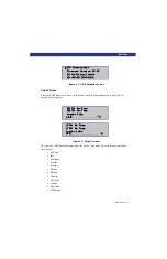
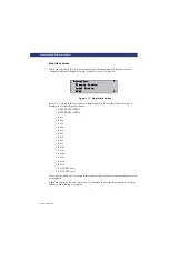
Figure 3-4. LTO Initialization Screen

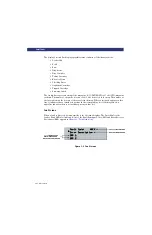
Default Screen

After the POST diagnostics have concluded successfully and initialization is complete, the 
default screen displays:

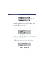
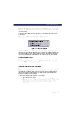
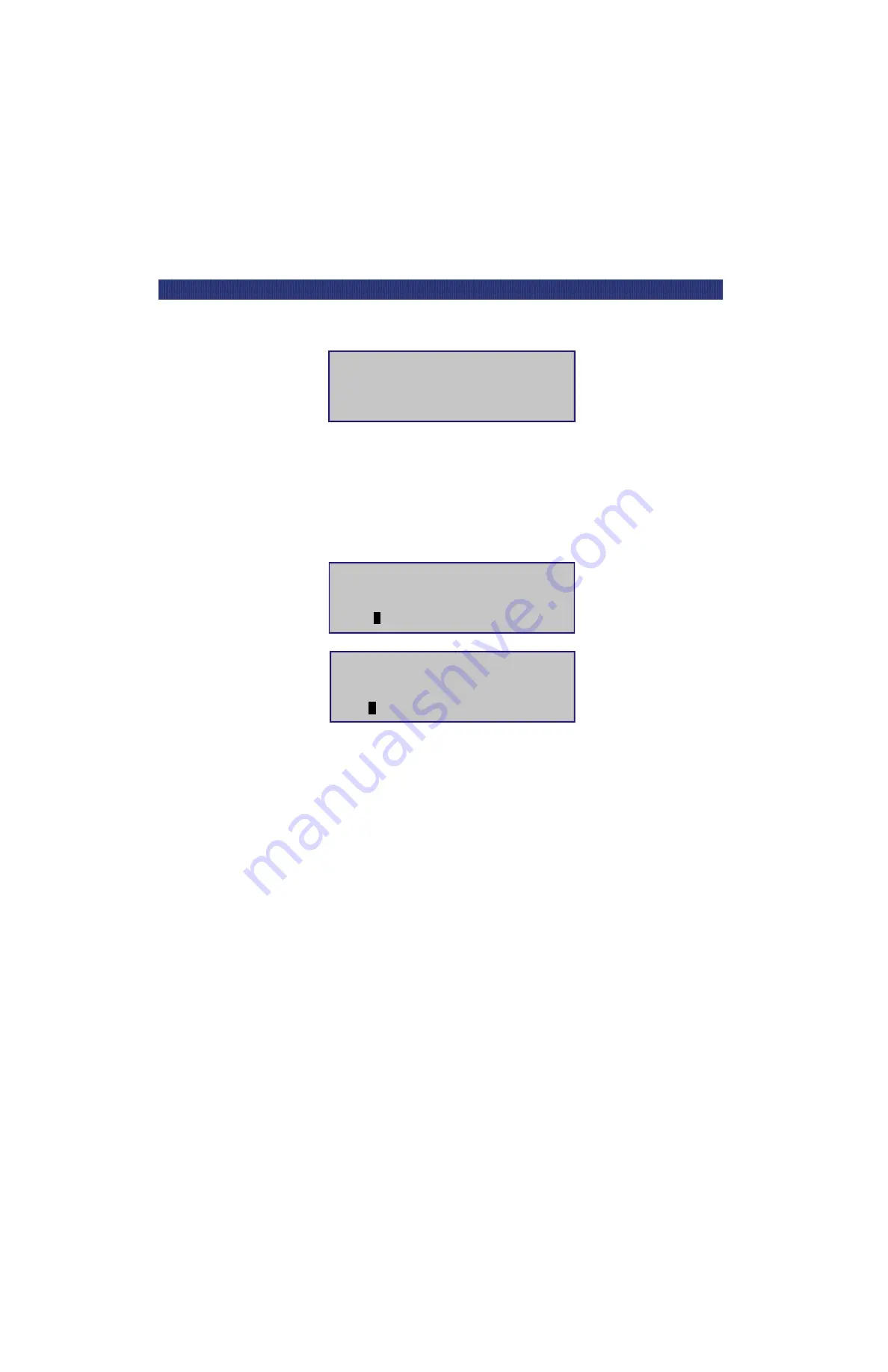
Figure 3-5. Default Screens

The first line of the Default Screens show the status of the drive. Possible status conditions of 
the drive are:

No Tape

Idle

Rewinding

Seeking

Reading

Writing

Erasing

Cleaning

Unloaded

Loading

Unloading

Calibrating.

LTO PowerLoader

LTO PowerLoader

LTO PowerLoader

LTO PowerLoader

Firmware Version XX.XX

Firmware Version XX.XX

Firmware Version XX.XX

Firmware Version XX.XX

u

u

u

u

Initializing Loader

Initializing Loader

Initializing Loader

Initializing Loader

01-JAN-02 08:01:01

01-JAN-02 08:01:01

01-JAN-02 08:01:01

01-JAN-02 08:01:01

SDLT1: No Tape

SDLT1: No Tape

SDLT1: No Tape

SDLT1: No Tape

Loader Idle

Loader Idle

Loader Idle

Loader Idle

1

11

1

u

u

u

u

_ _ _ _ _ _ _ _ _ _ _ _ _ _

t

15

15

15

15

SDLT2: No Tape

SDLT2: No Tape

SDLT2: No Tape

SDLT2: No Tape

LTO1: No Tape

LTO1: No Tape

LTO1: No Tape

LTO1: No Tape

Loader Idle

Loader Idle

Loader Idle

Loader Idle

1

11

1

u

u

u

u

_ _ _ _ _ _ _ _ _ _ _ _ _ _ _ _

t

17

17

17

17

LTO2: No Tape

LTO2: No Tape

LTO2: No Tape

LTO2: No Tape

Содержание LXLS10

Страница 1: ......

Страница 2: ...itness for a particular purpose Overland Storage may make improvements or changes in the product s or programs described in this manual at any time These changes will be incorporated in new editions o...

Страница 3: ...erLoader configuration options Chapter 3 Operation Describes front panel operations for the PowerLoader along with inserting and removing tape cartridges and tape require ments Chapter 4 Maintenance D...

Страница 4: ...xii u Preface PREFACE...

Страница 5: ...Installation Interfaces 2 2 Interface Cable Specifications 2 2 Connecting to the Host 2 3 Connecting to the Power Source 2 4 Configuration 2 5 Configuration Example Setting the SCSI ID 2 5 Configurat...

Страница 6: ...eens 3 4 Default Screen 3 5 Fault Screen 3 6 The DLT SDLT PowerLoader Menu Structure 3 7 The DLT SDLT PowerLoader Menu Structure 3 8 The LTO PowerLoader Menu Structure 3 9 The LTO PowerLoader Menu Str...

Страница 7: ...Cartridge 4 2 Installing a Cleaning Cartridge 4 2 Auto Clean Mode 4 2 Running the Cleaning Cartridge From the Front Panel 4 2 Removing the Cleaning Cartridge 4 4 Introduction 5 1 Diagnosing Problems...

Страница 8: ...iv TABLE OF CONTENTS CONT D...

Страница 9: ...ation Table 2 1 Connectors Terminators and Cables 2 2 Table 2 2 Power Cord Rating 2 4 Table 2 3 PowerLoader Configuration Options 2 9 Chapter 3 Operation Table 3 1 Control Panel Buttons 3 2 Table 3 2...

Страница 10: ...x LIST OF TABLES CONT D...

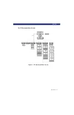
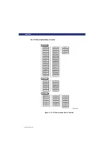
Страница 11: ...eens 3 5 Figure 3 6 Fault Screen 3 6 Figure 3 7 DLT SDLT PowerLoader Menu Structure 3 7 Figure 3 8 DLT SDLT PowerLoader Menu Structure 3 8 Figure 3 9 LTO PowerLoader Menu Structure 3 9 Figure 3 10 LTO...

Страница 12: ...re 3 32 SDLT Updated Default Screen 3 24 Chapter 4 Maintenance Figure 4 1 Main Menu 4 2 Figure 4 2 Maintenance Submenu 4 3 Figure 4 3 SDLT Cleaning Submenu 4 3 Figure 4 4 SDLT Cleaning Confirmation Sc...

Страница 13: ...re 1 1 PowerLoader PowerLoader The PowerLoader is a compact easy to use automated tape library designed for secure reliable unattended system backup Benefits The PowerLoader offers the following benef...

Страница 14: ...ng the front panel door Embedded diagnostics for verification and memory testing at power up and for user and Customer Engineer troubleshooting Features The PowerLoader features the following Front Pa...

Страница 15: ...is gained via the Control Panel menu Power Switch Push button switch used to apply power to the unit Press to power on or off Control Panel Includes LED Display Screen Four LED Indicators and Four Bu...

Страница 16: ...D with high density 68 pin series con nectors Fan Single forced air Provides optimum cooling for critical parts and prevents drive robotics motors and power supply from overheating Power Connector Sin...

Страница 17: ...pical Tape Cartridge Magazine The PowerLoader equipped with a 15 cartridge DLT SDLT or a 17 cartridge LTO magazine is accessible through the door at the center of the front panel It is protected from...

Страница 18: ...1 6 u Introduction TAPE CARTRIDGE MAGAZINE...

Страница 19: ...Configuration Setting Up the PowerLoader To set up the PowerLoader do the following Follow the directions in the shipping container to unpack the PowerLoader Save the packing materials in case you ne...

Страница 20: ...ING CAUTION XXXXXXXXXXXXXXXXXXX XXXXXXXXXXXXXXXXXXX XXXXXXXXXXXXXXXX Thi s dev ice c omp l ie s wi t h Part 15 o f FCC ru l e s O pera t i on i s xx xxx xxxxxxx xxxxxx xxx xxxxxx xxxxxxx xxx xxxxxx xx...

Страница 21: ...epresentative The cables you are using meet the required specifications for type and length The terminator type matches your system 2 If the PowerLoader is the only SCSI device you are connecting to t...

Страница 22: ...XXXXXXXXXXXXXX XXXXXXXXXXXXXXXX This device c o mpli e s with Part 15 o fF CCr ule s Op eration is xx xx x xxxxx xx x xxxxx xx x xxxxx x xx xxxxx x xx xxxxx x xx xxxxx x xx xxxxxxxx xxxxxxx xx xx x xx...

Страница 23: ...he button to scroll to the Configure submenu Press Enter to display the Configure submenu SDLT1 No Tape SDLT1 No Tape SDLT1 No Tape SDLT1 No Tape Loader Idle Loader Idle Loader Idle Loader Idle 1 1 1...

Страница 24: ...efaults are listed below in Table 2 3 Set Data Format This setting allows you to set the data format and enable or disable data compression This setting applies to the next or the currently loaded car...

Страница 25: ...s been unloaded by the host the operation continues by loading the cartridge in Slot 1 Recirculation will continue until an empty slot is encountered Set Element Base This setting allows you to set th...

Страница 26: ...the library to initiate SCSI Synchronous Negotiation with the host the default is No The library always responds to host initiated negotiation Set Transfer Rate can be set to 10 Mbytes sec 5 Mbytes se...

Страница 27: ...Mode Random Seq DLT SDLT or LTO Random Random Random Sequential Mode Normal Recirculate Normal Normal Normal Set Element Base Transport NNNN hex Storage NNNN hex Transfer NNNN hex 0000 0001 00F0 0000...

Страница 28: ...dard report Not Ready Custom report Good in Sequential Mod Standard Standard Standard Init Elem Status No Inventory Force Inventory Force Label Scan No Inven tory No Inven tory No Inven tory Unit Attn...

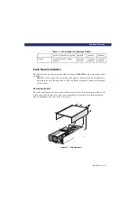
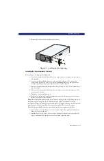
Страница 29: ...dule Removing the Skin The skin is held in place by four screws at the rear panel of the PowerLoader unit Remove the four screws slide the skin cover about one inch toward the rear then lift it from t...

Страница 30: ...der with the cover s front edge about one inch behind the front panel Slide the top cover forward as far as it will go 2 Install two of the four screws removed when you removed the skin Refer to Figur...

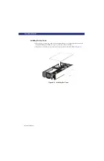
Страница 31: ...lide lock engages the intermediate slide b Continue to pull the outer slide towards the rear until the outer slide lock engages the intermediate slide Press down on the inner slide lock to permit the...

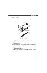
Страница 32: ...anel extensions are alike so there is no risk of confusing the parts on assembly 1 Place a panel extension against one side of the chassis so that the holes in the panel extension are aligned with the...

Страница 33: ...of the rear rail of the rack using two 10 32 screws and one nut plate 5 Tighten the screws installed in step 4 6 If they are not already locked pull the intermediate slides toward the front out of the...

Страница 34: ...hole in each panel extension Pull the PowerLoader outward and install 10 32 clip nuts 12 Slide the PowerLoader into the rack and install and tighten one 10 32 thumb screw through each panel extension...

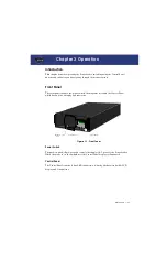
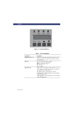
Страница 35: ...which has buttons a display and indicators Figure 3 1 Front Panel Power Switch The push on push off power switch controls the supply of AC power to the PowerLoader When the power is on the backplane o...

Страница 36: ...se to navigate through menu structure Escape Exit menus and submenus Enter Select desired option p Scroll up q Scroll down LED Indicators Ready green Indicates that the PowerLoader is ready to accept...

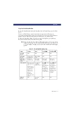
Страница 37: ...host with a SCSI Not Ready message until you exit the Menu Mode and the Ready light goes on Table 3 2 Control Panel Button Functions Screen Escape Enter Scroll Up p p p p Scroll Down q q q q At POST S...

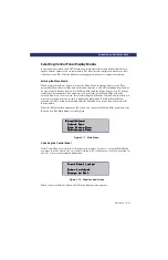
Страница 38: ...lines of 20 characters each to allow the use of easy to understand messages Many of these messages and their functions are described in this chapter Those displays that are described in other chapters...

Страница 39: ...erLoader Firmware Version XX XX Firmware Version XX XX Firmware Version XX XX Firmware Version XX XX u u u u Initializing Loader Initializing Loader Initializing Loader Initializing Loader 01 JAN 02 0...

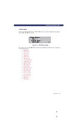
Страница 40: ...ars on this line it indicates that a cartridge is present in the corresponding slot of the magazine An underline indicates there is no cartridge present in that slot Fault Screen When a fault is detec...

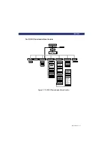
Страница 41: ...gnostics Cartridge Cycle Friction Test Tach Feedback Scanner Feedback Demo Menu Flash Update Novram Update Clock Update Flash SDLT Set Data Format Set SCSI Library Parity Library Bus ID SDLT1 Bus ID S...

Страница 42: ...Init Elem Status Unit Attn Report Boot Version Flash Type Baud Rate Barcode Reader Label Size Label Alignment Abort Move Status SCSI Mode Post Rec vd Error TApe Alert Mode Cln Cart Count DLT SDLT1 Sl...

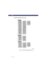
Страница 43: ...Set Data Format Set SCSI Library Parity Library Bus ID DLT1 Bus ID DLT2 Bus ID Set Library Mode Set Element Base Transport Storage Transfer Set Identification Vendor ID Product ID Set Baud Rate Set Se...

Страница 44: ...Elem Status Unit Attn Report Boot Version Flash Type Baud Rate Barcode Reader Label Size Label Alignment Abort Move Status SCSI Mode Post Rec vd Error TApe Alert Mode Auto Home LTO1 LTO2 Slot 1 Statu...

Страница 45: ...n Menu The Show Status Menu remains accessible It may be displayed from the Default Screen at any time by pressing the Escape button When the Default Screen appears on the screen you can enter the Men...

Страница 46: ...ng the Escape button once returns to the Default Screen Menu Structure Navigation To select a submenu scroll the u to the desired line using the p and q buttons Press the Enter button to confirm your...

Страница 47: ...2 Map Info Scroll up or down with the p and q buttons and press the Enter button to select the item Library Status Submenu When the Library option is selected the Library submenu screen appears Figure...

Страница 48: ...er Address Serial Number Wide SCSI enable SCSI Bus ID SCSI Bus Parity Negotiation Mode Transfer Rate Unload Mode Auto Clean Mode Reserved Slots Mode Page 1F Length TUR Reporting Init Element Status Un...

Страница 49: ...play the Drive Status options Tape Motion Product Type Tape Format Compression SCSI Bus ID Drive Revision Controller Revision Cartridge Present Hardware Error Write Protected Serial Number Read Compre...

Страница 50: ...LT1 SDLT1 or LTO1 DLT2 SDLT2 or LTO2 Slot1 Slot2 Slot3 Slot4 Slot5 Slot6 Slot7 Slot8 Slot9 Slot10 Slot11 Slot12 Slot13 Slot14 Slot15 Slot16 LTO only Slot17 LTO only If you have reserved slots to compl...

Страница 51: ...bed in Chapter 2 Installation Show History Menu The Show History Menu enables the operator to review the history of the module You can retrieve the configuration history the original configuration as...

Страница 52: ...accept it Press the Escape button again to return to the Main Menu and again to return to the Default Screen Unlocking the Control Panel To unlock the Control Panel enter the security code from the Pa...

Страница 53: ...e item selections on the Library Status submenu of the Show Status Menu It is also displayed on line 2 of the POST Screen and the Initialization Screens Inserting and Removing Cartridges You must remo...

Страница 54: ...prevents removal of the magazine turn the power off for 30 seconds Power up while continuously pressing the p button Continue to hold the button until all of the indicators on the Control Panel light...

Страница 55: ...PowerLoader with that orientation Figure 3 24 Tape Magazine with Cartridges Installed Tape Requirements Cartridge Handling and Storage Store the tape cartridge vertically until you select it for use D...

Страница 56: ...isplays Figure 3 26 Main Menu From the Load Unload option press the Enter button to display the first Load Unload submenu Figure 3 27 Load Unload Initial Submenu INITIAL SCREEN FROM LINE The list on l...

Страница 57: ...dicating you can select a destination Figure 3 29 SDLT Load Unload To Entry Screen From line 4 press the q button As soon as you press the q button three things happen The list scrolls down one item o...

Страница 58: ...ot 4 is full Figure 3 32 SDLT Updated Default Screen From SDLT1 From SDLT1 From SDLT1 From SDLT1 To Slot 4 To Slot 4 To Slot 4 To Slot 4 ENTER to Execute ENTER to Execute ENTER to Execute ENTER to Exe...

Страница 59: ...odule are intended for the user This chapter tells you how to clean the drives The Demo Menu is described in Chapter 5 Troubleshooting Cleaning Cartridge The cleaning cartridge is similar in appearanc...

Страница 60: ...owerLoader using the procedure described in Chapter 3 Operation Inserting and Removing Cartridges 3 Remove any cartridge present in Slot 1 the slot nearest to the handle or in Cleaning Slot 1 the firs...

Страница 61: ...4 will refer to Cleaning Slot1 which is the first reserved slot The Clean Confirmation Screen appears as shown below Figure 4 4 SDLT Cleaning Confirmation Screen As the confirmation screen indicates t...

Страница 62: ...load it using the Load Unload Menu as described in Chapter 3 Operation 2 Remove the magazine from the PowerLoader using the procedure described in Chapter 3 Operation Inserting and Removing Cartridges...

Страница 63: ...not get an error code on the Control Panel To identify an error as this type of problem check your installation and configuration setup refer to Chapter 2 Installation General Drive Errors General dri...

Страница 64: ...ecovery Procedures Use Table 5 1 to identify and correct errors Table 5 1 Error Recovery Procedures ERP Procedure C Cycle power to the drive using the AC switch on the front panel of the module Wait 3...

Страница 65: ...e trace serial port The loopback test of the baud rate divisor registers or one of the expected 0 bit tests failed C D G 0301 Novram Init Error Enter to Reboot or Power Down to Clear HARD fault The fi...

Страница 66: ...nitialization C D G 0603 Clock Download Error Press Enter to Clear SOFT fault The initialization of the real time clock via the trace serial port failed F 0701 Slv Comm Open Error Enter to Reboot or P...

Страница 67: ...r to Clear SOFT fault no pending interrupt was set F 1009 SCSI Invalid Int Press Enter to Clear SOFT fault the SCSI controller chip posted an unrecognized interrupt type F 1020 No Active Command Press...

Страница 68: ...an available message structure for an encapsulated SCSI packet F 1051 No Free Tids Press Enter to Clear SOFT fault the SCSI process cannot get a transaction id because all id are currently in use F 2...

Страница 69: ...led Enter to Reboot or Power Down to Clear HARD fault Watch Dog muzzle in place unused in LTO C D G 200C Cart Unaccessible Press Enter to Clear Used to inform the Web TLC that the move medium command...

Страница 70: ...Reboot or Power Down to Clear HARD fault can t communicate with drive C D G 2032 DRV Timeout Error Enter to Reboot or Power Down to Clear HARD fault can t communicate with drive C D G 2033 DRV Timeout...

Страница 71: ...e free pool empty C D G 2060 Calib Error Port 0 Enter to Reboot or Power Down to Clear HARD fault Multi module passthru elevator calibration error does not apply to LTO loader C D G 2061 Calib Error P...

Страница 72: ...Reboot or Power Down to Clear Excessive gripper tach errors AIT libraries only C D G 3004 Passthru Tach Errors Enter to Reboot or Power Down to Clear Excessive passthru elevator tach errors C D G 300A...

Страница 73: ...ccupied C D G 3040 Motor Firmware Error Enter to Reboot or Power Down to Clear HARD fault F W err invalid state value unused C D G 3100 Picker Jammed Enter to Reboot or Power Down to Clear HARD fault...

Страница 74: ...to Clear SOFT fault A front panel load or unload command could not find any tapes to move All drives and slots are empty F 5002 All Drvs Slots Empty Press Enter to Clear SOFT fault A front panel load...

Страница 75: ...ad Calender Setting Press Enter to Clear SOFT fault Bad calendar setting unused in LTO F 5032 Bad Setting Press Enter to Clear SOFT fault Bad Setting F 5033 Set Density Failed Press Enter to Clear SOF...

Страница 76: ...lear HARD fault EnQ Without IDs C D G 6005 DeQ Without IDs Enter to Reboot or Power Down to Clear HARD fault DeQ Without IDs C D G 6006 EnQ Null Pointer Enter to Reboot or Power Down to Clear HARD fau...

Страница 77: ...ter to Reboot or Power Down to Clear HARD fault Comm Port Ack Error C D G 6021 Slave RTS Still Set Enter to Reboot or Power Down to Clear HARD fault Slave RTS Still Set C D G 6022 Slave Addr Invalid E...

Страница 78: ...e Re Boot Failed F 6035 Slave Update Err Press Enter to Clear SOFT fault Slave Update Err F 6036 Invalid Image Size Press Enter to Clear SOFT fault Invalid Image Size F 6037 Command Timeout Enter to R...

Страница 79: ...D fault Packet Length Error C D G 604C Slave Address Error Enter to Reboot or Power Down to Clear HARD fault Slave Address Error C D G 8001 Bad Cartridge Press Enter to Clear SOFT fault the drive was...

Страница 80: ...r Down to Clear HARD fault The boot code was unable to open the serial trace port C D G B011 Boot UART 1 Error Power Down to Clear HARD fault The boot code was unable to open the LTO drive serial port...

Страница 81: ...ss Enter to Clear SOFT fault host aborted download due to an incompatible image F F007 Flash Invld SCSI Cmd Press Enter to Clear SOFT fault the transfer length requested in a SCSI Write Buffer command...

Страница 82: ...p button while Demo 1 is running the PowerLoader loads a cartridge into the drive unless it is full If you press thep button again the cartridge is unloaded from drive and returned to the magazine Dem...

Страница 83: ...0 A 1 8 1 0 A 1 8 1 0 A Line Frequency 50 60 Hertz 50 60 Hertz 50 60 Hertz Mechanical Specifications Desk Top Height 8 00 in 20 32 cm Width 17 3 in 43 94cm Depth 29 in 73 66 cm Weight 69 lbs 31 29 kg...

Страница 84: ...Class B digital apparatus complies with Canadian ICES 003 Industrie Canada Cet appareil num rique de la classe B est conforme la norme NMB 003 du Canada Acoustic Emissions Drive In Use Intermittent r...

Страница 85: ...ent off and on the user is encouraged to try to correct the interference by one or more of the following measures Reorient or relocate the receiving antenna Increase the separation between the equipme...

Страница 86: ...A 4 u Specifications SPECIFICATIONS Declaration of Conformity...

Страница 87: ...mag azine cartridges not included 106064 002 Rackmount adapter kit 103434 001 Browser compatible remote control inter face Spares FRUs 108136 001 Fan Assy LX 108138 001 Power Supply LX replaced by 108...

Страница 88: ...HVD Controller LXL M S 108237 001 Cable Drive 1 SE HD LXM 108237 002 Cable Drive 2 SE HD LXM 108237 003 Cable Drive 1 LVD SE LXM 108237 004 Cable Drive 2 LVD SE LXM 108258 001 Power Supply Assy 10827...

Страница 89: ...dures 5 1 F Fault Screen 3 6 Fault Symptom Codes FSC 5 3 Features 1 2 Firmware Revision displaying 3 18 Front Panel 1 3 3 1 G General Drive Errors 5 1 I If You Drop a Cartridge 3 21 Installing 2 1 Ins...

Страница 90: ...Index 2 INDEX...

Отзывы: