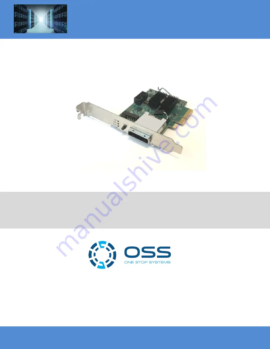
PCIe x4 Gen 3, Switch-based Cable Adapter
OSS-PCIe-HIB38-x4
User Manual
SKU: OSS-PCIe-HIB38-x4
www.onestopsystems.com
Страница 1: ...PCIe x4 Gen 3 Switch based Cable Adapter OSS PCIe HIB38 x4 User Manual SKU OSS PCIe HIB38 x4 www onestopsystems com ...
Страница 2: ...ower Connectors 10 2 6 2 High Power PCIe card installation 10 2 7 Plug in Power to Expansion unit 10 2 8 Power ON Host computer 11 2 9 Hardware Check 11 3 Other Technical Information 12 3 1 Dipswitch Setting SW3 12 3 2 Bracket LEDS 12 4 FAQ s 13 5 How to Get More Help 14 5 1 Contacting Technical Support 14 5 2 Returning Merchandise to OSS 14 5 3 Online Support Resources 15 6 Appendix A Compliance ...
Страница 3: ...One Stop Systems OSS PCIe HIB38 x4 3 7 7 1 PCI Express Performance Table 21 7 8 Power 22 ...
Страница 4: ...p to help you CAUTION Used to indicate and prevent the following procedure or step from causing damage to the equipment WARNING Used to indicate and prevent the following step from causing injury DANGER or STOP Used to indicate and prevent the following step from causing serious injury or significant data loss Disclaimer We have attempted to identify most situations that may pose a danger warning ...
Страница 5: ...ter 1 Before taking covers off a computer perform the following steps 2 Turn off the computer and any peripheral devices 3 Disconnect the computer and peripheral power cords from their AC outlets or inlets in order to prevent electric shock or system board damage In addition take note of these safety guidelines when appropriate To help avoid possible damage to systems boards wait five seconds afte...
Страница 6: ... which can include wrist straps and smocks when servicing equipment You can also take the following steps to prevent damage from electrostatic discharge ESD When unpacking a static sensitive component from its shipping carton do not remove the component s anti static packaging material until you are ready to install the component in a computer Just before unwrapping the anti static packaging be su...
Страница 7: ...ass Cable x4 OSS PCIe CBL x4 qty 1 4 Gen3 x8 PCIe slot computer motherboard 5 SFF 8644 cables qty 2 Cable connectors are keyed so that you cannot insert them incorrectly 1 1 Host card Configuration For Host mode Set the dipswitch SW3 1 to OFF position 1 2 Target card Configuration For target mode Set the dipswitch SW3 to ON ...
Страница 8: ... party PCIe card 6 Connect power to expansion system a Attach Power Cord 7 Power on Computer 8 Hardware Check 9 Verify Installation via Operating System NOTE It is highly recommended to install any 3rd party PCI E cards High Power PCIe cards after you have verified and tested that the OSS expansion chassis is functional When installing 3rd Party PCIe cards start with one card first just to see if ...
Страница 9: ...x16 x8 or x4 PCIe slot in the host computer 2 5 Install Target Adapter card Install the Target adapter card in the designated Upstream slot of the expansion board Do not install the Target card in the downstream slot the card only works in the Upstream slot 2 6 Connect Cable Connect the x4 Ipass cable to the Host card and connect the other end of the cable to the Target card Make sure the cable is...
Страница 10: ...e 4 pin Molex AUX power connectors that can be used for providing extra power to cards and two 6 2 pin PCIe connectors for GPUs 2 6 2 High Power PCIe card installation High Power PCIe cards also known as High End PCIe cards such as GPUs and other similar type of card requires additional power or AUX Power to operate High power PCIe cards or GPUs that requires auxiliary power should come with power...
Страница 11: ...nate as solid green 2 9 Hardware Check Check the bracket LED on both Host and Target cards Target and Host card LEDs CBL and CE LEDs are illuminated as solid green The CE LED could be ON as solid green or blinking depending on the LINK i e Gen1 or Gen2 CBL LED when ON it indicates that the cable is recognized On the Host card HP_PWR LED D4 ON as solid blue ...
Страница 12: ...uter ON Target Mode card is installed in the OSS expansion board in a Upstream PCIe slot SW2 OFF Target Power Enabled by Host Default ON Target Enabled Regardless of Host SW3 OFF Automatic Speed Negotiation Default ON Force PCIe 1 1 Speed SW4 OFF Backplane Type OSS Backplane ON Backplane Type Magma 3 2 Bracket LEDS Dipswitch Description CE Card Edge Link Status CBL Cable Link Status ATN Hot Plug A...
Страница 13: ...ch to link at lower link speeds SW3 4 BACKPLANE Used in target mode only When using Magma produced backplanes this must be ON OSS backplanes must be OFF Question 4 Is the card compatible with devices that run over PCIe Gen2 x4 Answer Yes this card version was able to link to Gen 2 x4 but there are design issues that may hampering proper operation Question 5 Which LED are lighting when the cable an...
Страница 14: ...t possible damage Note Expansion board and PCIe PCI cards that arrive damaged in shipment will not be covered under warranty 5 2 Returning Merchandise to OSS If factory service is required a Service Representative will give you a Return Merchandise Authorization RMA number Put this number and your return address on the shipping label when you return the item s for service OSS will return any produ...
Страница 15: ...hooting methods compatibility FAQ documentation and product technical information Support Product Knowledgebase FAQ https www onestopsystems com knowledge center Manuals Documents If you need technical support product assistance or have a technical inquiry we encourage you to submit it on line using our Technical Support Form here is the link Submit Technical Support If you need to send a unit for...
Страница 16: ...t 15 of the FCC Rules Operation is subject to the following two conditions 1 this device may not cause harmful interference and 2 this device must accept any interference received including interference that may cause undesired operation Changes or modifications not expressly approved by the party responsible for compliance could void the user s authority to operate the equipment NOTE The assemble...
Страница 17: ...tell how many lanes a slot uses by its length http i imgur com JxN1FDm jpg The more lanes the more bandwidth it provides 7 2 How PCI Express Works A PCI Express PCIe link comprises from one to 32 lanes Links are expressed as x1 x2 x4 x8 x16 etc The link is negotiated and configured on power up More lanes deliver faster transfer rates most graphics adapters use at least 16 lanes in today s PCs The ...
Страница 18: ... 18 7 4 PCI Express Links and Lanes When computer starts up the BIOS detects and enumerates all devices that are plugged into the CPU motherboard It then identifies the links between the devices and creating a map of where the traffic will go and negotiating the width of each link ...
Страница 19: ...rmit physically longer cards and negotiate the best available electrical and logical connections 8 5 1 PCI Express Sample Connectors The number of lanes actually connected to a to a slot may also be less than the number supported by the physical slot size An example is a x16 lot that runs at x4 which will accept any x1 x2 x4 x8 or x16 card but only provides four lanes Its specification may read as...
Страница 20: ...00MB s of actual data transfer per lane PCIe 3 0 is twice the speed of PCIe 2 0 having a per lane throughput that is only 60 percent more than PCIe 2 0 s 5GT s PCIe 3 0 use more efficient encoding scheme called 128b 130b so the overhead is much less only 1 54 percent This means that a single PCIe 3 0 lane at 8GT s can send 985B s A PCIe 3 0 x4 connection 3 94GB s should have nearly the same bandwi...
Страница 21: ...ytes per second B s you need to divide it by eight since a byte is a group of eight bits However because of the 8b 10b encoding we need to make this division by 10 rather than eight This is the reason why with a clock of 2 5 GHz and 5 GHz the x1 bandwidth of these connections are 250 MB s and 500 MB s respectively and not 312 5 MB s and 625 MB s The two extra bits added are called overhead and the...
Страница 22: ...aphics power connectors PCI Express x16 Graphics 150 W ATX Specification Published in October 2004 this standard defines a six pin 2x3 auxiliary power connector capable of delivering an additional 75 W to a graphics card directly from the power supply for a total of 150 W to the card PCI Express 225 W 300 W High Power Card Electromechanical Specification Published in March 2008 this standard defin...
Страница 23: ...One Stop Systems OSS PCIe HIB38 x4 23 ...