Ones Stop Systems
EB7-X8G2-RAS | 2 Hardware Installation
16
2.5.2 Hardware Check
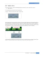
As your computer starts up, you will see LINKUP lights appear on the back o f the chassis near the iPass connector.
Green LINK LEDs
0 – Connection between host and chassis has been established
1 through 7 – PCI Express Cards have been found in respective slots
Linkup 0 represents the EIF card connected “uplink” with the host’s HIF. Linkup 1 through 7 light up as soon as PCIe cards have been found in
the 7 respective expansion slots. In the above example, LED 0 represents the fact that the uplink is connected, while LEDs 2, 4 and 5 represent
three PCIe cards that have been installed in slots # 2, 4 and 5 respectively. The Linkup LEDs represent only an initial connection/handshake
between the chassis and host PC. A successful linkup does not represent transfer or exchange of data. For that the chassis features the activity
LEDs. The activity LEDs are visible from the inside of the chassis and indicate activity by blinking. An example is shown below:
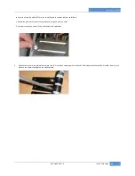
In this case linkup LEDs (on the right) are on for uplink (0) and for slots 3, 6 and 7. Activity LEDs (on the left) are blinking only for uplink (0) and
slots 6 and 7. That tells us that the PCIe card in slot 3 is linked but idle (i.e. no data is currently transmitted to or from it).

