background image

One Stop Systems 


4U Pro 10 Slot 


                                               49


16 

Important Technical Information 

16.1  

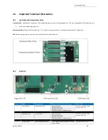
Upstream and Downstream Slots 

 Upstream Slot

:  Also known as target slot. This is the designated slot for the Target adapter card. This slot is designed for the Target card only. 


Slot0  is the default Upstream slot.  

Downstream Slots:

 These are PCIe card slots # 1, 2, 3, 4 and 5. You cannot use any of the downstream slots for Target card. 

Slot 5

 can be programmed to operate as an Upstream slot or Downstream slot. 


16.2 

Slot LEDs 


Item 

Name 

Description 

When Lit (Solid Green or Blinking) 

When Off 

Target Slot LED 

Upstream  Slot LED 

Solid = Gen4 Link 

OFF - Not Linked / No Card 
present in the slot 

Blink 2Hz = Gen3 Link 
Blink 1Hz = Gen2 Link 
Blink 0.5Hz = Gen1 Link (Slow Blinking) 


Downstream LED 

PCIe slot LEDs 

Solid = Gen4 Link 

OFF - Not Linked / No Card 
present in the slot 


Blink 2Hz = Gen3 Link 


Blink 1Hz = Gen2 Link 


Blink 0.5Hz = Gen1 Link (Slow Blinking) 


Aux Power LED 

Auxiliary Board power LED 

This is GREEN, denotes existence of auxiliary 
power +5VAUX 

Board is at fault / error 

Содержание 4UP 10-SLOT GEN4

Страница 1: ...INSTALLATION GUIDE 4UP 10 SLOT GEN4 4UP 10 SLOT Gen4 www onestopsystems com ...

Страница 2: ... Host Card Installation 20 6 1 Host Card Configuration 20 6 2 Dip switch Settings 22 7 GPU PCIe Cards Installation 23 7 1 Install PCIe card GPUs 24 7 2 Connect Aux Power Cables 24 7 3 Auxiliary Cable Management 25 8 Connect Link Cables 26 8 1 Mini SAS HD SFF 8644 Cable Installation 26 8 1 1 x16 Configuration FOUR cables 26 8 1 2 x8 Configuration TWO cables 27 8 1 3 x4 Configuration ONE cable 28 8 ...

Страница 3: ...I 46 15 1 Connect Ethernet Cables 46 15 2 Locate Mac Address IP Address 47 15 3 Start Internet browser 48 16 Important Technical Information 49 16 1 Upstream and Downstream Slots 49 16 2 Slot LEDs 49 16 3 Board LEDs 50 16 4 Slot Type 50 16 5 PS_ON 50 16 6 ARF6 Connector 51 16 7 Slot Number and Port Mapping 51 16 8 Power Cords 52 16 8 1 Specifications 52 16 8 2 Power cord socket and voltage tables ...

Страница 4: ...17 Troubleshooting 66 17 1 Device is not detected or recognized 66 17 2 My PCIe devices are showing UP with a Yellow Exclamation mark 66 17 3 No link between host and target cards 66 17 4 Broken OSS Backplane 66 17 5 My PCIe cards are not detected 67 18 How to Get More Help 67 18 1 Contacting Technical Support 67 18 2 Returning Merchandise 67 18 3 Third Party Hardware Software Support Policy 68 18...

Страница 5: ...ll slots are downstream to a single upstream Cooling Operational Temperature 0 35 C Operational Humidity 10 90 relative humidity Operational Altitude 0 10 000 feet above sea level Storage Temperature 40 C 71 C Fans 3x 180CFM 120mm fans Default PWM controlled based on built in temperature sensors Optional IPMI system monitoring and control Power Options Single Dual AC 1600W Single Dual DC 1600W Sys...

Страница 6: ...Features PCIe Gen4 architecture Semi rugged frame design Dynamic fan speed control Configurable slot and host uplinks to optimize throughput Integrated IPMI based system monitoring AC and DC power inlet options 1 2 4UP Architecture 10 Slot ...

Страница 7: ...Pro 10 Slot 7 1 3 PCIe Slots Slot Type Closed ended PCIe slot connector all the slots are x16 mechanical Six x8 electrical slots slots 1 2 3 4 5 and 6 Three x16 electrical slots slots 0 7 and 8 1 4 Backplane Block Diagram ...

Страница 8: ...One Stop Systems 4U Pro 10 Slot 8 1 5 Dimensions ...

Страница 9: ...ion 7 PowerSupply Modules 8 Removable Fans 9 Target Cards 10 RearRJ45 Port Access to IPMI Number Description 11 IPMI Module Board 12 Fan Power Connectors 13 Auxiliary Power Connectors 10 qty 14 PowerSupply Housing 15 Backplane OSS 538 board 16 Passive Heatsink PCIe Switch 17 ARF Connectors One Stop Systems 4U Pro 10 Slot 9 1 6 Parts Overview ...

Страница 10: ... 18 12V Input Power Connectors 19 Upstream Slots Target Slots 20 Downstream Slot PCIe Card Slots Options Slots Operates as either Downstream or 21 Upstream dependingon the configuration One Stop Systems 4U Pro 10 Slot 10 ...

Страница 11: ...LED A single x4 SFF 8644 cable must be inserted into port 0 of the Target card On the Host card side you can plug in a single x4 cable to any port as long as the Host card switch is set to x4 mode When using two x4 SFF 8644 cables it must be connected to port 0 and port 1 of the Target card only On the Host card side plug in the two cables to port 0 and portt 1 OR port 2 and port 3 ...

Страница 12: ...icator when slot is populated or not Solid green when card is present Off when no card 9 Target Slot LED LED status indicator for Target card Solid green when Gen 4 adapter card is installed 10 Upstream Port Target Slot Designated slot for Target card only 11 Dip Switches For slot configuration 12 Board LEDs LED status indicator for the board 13 FPGA Connector FPGA Programming connector 14 PS_ON E...

Страница 13: ...Systems 4U Pro 10 Slot 13 1 9 Slot Configurations Configuration 1 Default slot configuration One Upstream slot and five Downstream slots You must have the ARC6 cables attached between the edge of the board and the slot connectors under the backplane Without those ARC6 cables nothing will work in SLOT 5 Configuration 2 Two Upstream slots Slot 0 and SLOT 5 with two partitions Slot 0 Partition 1 with...

Страница 14: ...1 Upstream Slot 9 Downstream slots 2 Non oPerational slots One Stop Systems 4U Pro 10 Slot 14 Configuration 3 Two backplanes are daisy chained together ...

Страница 15: ...card and Target card 5 Downstream slots 5 x16 slots Slot 1 2 3 4 and 5 Configuration 2 OSS 538 backplane is linked to two host computers see diagram below Two partitions two Upstream slots Slot 0 and SLOT 8 with a total of 4 downstream slots Slot 0 Partition 1 with two Downstream slots o 2 x16 slots Slot 1 and 2 Slot 8 Partition 2 with two Downstream slots o 2 x16 slots Slot 3 and 4 ...

Страница 16: ... are daisy chained together and it is linked to a single host computer 9 Downstream slots 1st backplane 4 downstream slots 4 x16 slots slot 1 2 3 and 4 1 non operational slot slot 5 2nd backplane 5 downstream slots 5 x16 slots slot 1 2 3 4 and 5 1 non operational slot slot 5 ...

Страница 17: ...d have another card that is configured as host card b Check the dipswitches make sure it is set to host mode prior to installing the card 4 Install PCIe GPU cards a Plug in your PCIe or GPU cards in the expansion unit 5 Connect the external link cables a Plug in the Mini SAS HD SFF 8644 cables between Target and Host cards 6 Plug in the power cords a The unit is supplied power cord s You should ha...

Страница 18: ...sis 2 Slide the enclosure cover towards the back of the unit to disengage it from the guides until it clears the back and then lift the cover off 5 Target Card Installation By default the Target cards are already in the unit See photos below for the correct slot location where the Target cards are installed ...

Страница 19: ... to set the card switches to Target mode Find the SW1 on the card and set the switches to target mode see diagram photo below Move SW1 1 and SW 2 to ON position Once the card is configured install the Target card in the designated target slot upstream slot 0 Photo below shows the exact location of the Upstream slot Slot 0 Make sure the card is firmly seated in the card slot and secured ...

Страница 20: ...ion mode You can leave the switches to default or you can set the switches SW1 and SW2 on the card for the desired Host operating mode See Host Card Configuration section for more details 6 1 Host Card Configuration The following diagrams photos are the switch settings for the Host card x16 Dip switch Settings SW1 2 ON 5 ON SW2 1 ON 2 ON x8 Dip switch Settings SW1 2 ON 5 ON SW2 1 OFF 2 ON or 2 OFF...

Страница 21: ...mage the card during installation Align the host card edge connector on top of the PCIe slot and carefully push the card down until it is firmly seated Secure the card with the screw Below is a photo of a x16 PCIe slot connectors The photo on the right is a PCI E 3 0 x16 slot The specification of the PCIe slot is printed on the board next to connector for easy identification Use a x16 PCIe slot fo...

Страница 22: ... SWi 5 must always be ON Auto mode not supported SW2 3 to 6 are not used Legacy backplane Magma Gen3 backplane One Stop Systems 4U Pro 10 Slot 22 6 2 Dip switch Settings ...

Страница 23: ...e Upstream slot aka Target Slot Slots 1 2 3 and 4 are downstream slots Slot 5 is an option slot Configurable to upstream or downstream modes o Downstream mode Use downstream slot for an end point device i e video card Ethernet sound card and etc o Upstream mode Use upstream slot for an OSS Gen4 target card only IMPORTANT You need the ARC6 cables attached between the edge of the board and the slot ...

Страница 24: ...ver s prior to installing the hardware Install GPU card in the downstream slot one at a time Align the card on top of the slot Gently push the card down until it is firmly seated Secure the GPU or the PCIe cards 7 2 Connect Aux Power Cables Plug in the appropriate auxiliary power cable to each GPU Use the supplied compatible aux cable for your GPU Photos below is an example of an auxilirary power ...

Страница 25: ...s on the power distribution board Perform the same installation methods for the remaining GPUs 7 3 Auxiliary Cable Management Route the cables away from the fan Make sure the cables are not blocking the air flow Use a zip ties or tie wraps to tuck the cables in You can also use a Velcro strap to hold or tie down the cables ...

Страница 26: ...nnect two link cables Configured to operate at x4 mode connect one link cable See the following cable configurations for more details 8 1 1 x16 Configuration FOUR cables Plug in the 1st cable to Port 0 Top port on both Target and Host cards Plug in the 2nd cable to Port 1 on both Target and Host cards Plug in the 3rd cable to Port 2 on both Target and Host cards Plug in the 4th cable to Port 3 Bot...

Страница 27: ...st cards On the host card side you can also use the two bottom ports PORTS 2 3 1st Cable to PORT 2 2nd cable to PORT 3 Note The two cables on the TARGET card must remain connected on PORT 0 and PORT 1 See diagrams below as an example Photo B1 The two cables are connected on the Target card PORTS 0 and 1 The other end of the cables are connected on the Host card PORTS 2 and 3 Photo B2 The two cable...

Страница 28: ...her end of the cable stays connected on Target card PORT 0 Photo A1 Cable is connected on the Target card PORT 0 The other end of the cable is connected on the Host card PORT 1 Photo B1 Cable is connected on the Target card PORT 0 The other end of the cable is connected on the Host card PORT 2 Photo C1 Cable stays connected on the Target card PORT 0 The other end of the cable is connected on the H...

Страница 29: ...0 Slot 29 Diagrams below are different x4 cable configurations 8 2 Disconnecting Mini SAS HD SFF 8644 Cable To disconnect the link cable pull back the PLASTIC thumb tab to release metal clamp while slowly pulling the cable out ...

Страница 30: ... the power cord supplied with the unit connect the power cord to the back of the power supply Ensure that the system s power supply unit is fully secured before connecting the power cord You should have either the 125v or the 250v power cord If you only have the 125V power cord and you require the 250V power cord please contact our Sales Team sales onestopsystems com to place an order Power Cord V...

Страница 31: ... LED PSU Good Amber LED PSU fault or power issue If Power LED indicator is showing Amber in color it indicates a fault or power issue The two front LEDs the OSS logo will illuminate as blue and the STANDBY MAIN PWR will come ON as solid green ...

Страница 32: ...n a x16 Gen3 Gen4 PCIe slot and the cables are firmly connected Upon powering up the Host computer it will initialize a link between the target and the host The Link LED on both target and host cards will illuminate as solid green Solid green Link LED it means the negotiated link width between host and target card is x16 Blinking green Link LED the link width is x8 ...

Страница 33: ...LOT LED when a PCIe card is installed in the target slot the LED will illuminate as solid green A fully operational back plane will illuminate the following LEDs Check LEDs D9 D8 and D1 make sure they are correctly illuminated D9 Blinking green LED 1 D8 Solid green LED 0 D1 AUX power solid green ...

Страница 34: ...he backplane is not programmed Or the FW image is corrupted RED LED CR1 PEDRT The backplane is not getting initialized due to Faulty Target card Board is not programmed One Stop Systems 4U Pro 10 Slot 34 11 2 Fault LEDs RED When the RED LED is lit on the backplane it signifies fault or error ...

Страница 35: ...en D4 LED1 Solid green D6 LED2 Solid green D8 LED3 Solid green CHO Link LED Solid green D9 Aux Power Solid green x16 configuration Four x4 Cables connected CHO LED will illuminate as solid green indicates of a stable LINK between Target and Host cards When there is no link between Target and Host cards the CHO LED is turned OFF The C9 Aux power LED will illuminate as solid green which is an indica...

Страница 36: ...hy AUX Power Good PWR D10 ON Blinking Green AUX D9 ON Solid Green One Stop Systems 4U Pro 10 Slot 36 11 4 Adapter Card LED Definitions LEDs for SFF 8644 Cable Link cases 1 Target mode x16 D1 is the link indicator 2 Host Mode x16 D1 is the link indicator 3 Host Mode x8x8 D1 or D5 are the link indicators one for each corresponding group of two SFF cages 4 Host Mode x4x4x4x4 D1 D3 D5 D7 are the link ...

Страница 37: ... the PSU is working properly See photos below for the location of the PSU DC GOOD led 11 7 Front LED There are three visible LEDs located on the front of the unit The LOGO led will illuminate as solid BLUE Standby MAIN PWR Solid green when unit is fully powered ON Red when the unit is on standby mode IPMI This is optional Will only illuminate as solid green when IPMI module is installed in the uni...

Страница 38: ...the LED should be amber During protection mode 5Vsb rail the LED should be OFF When protection is cleared the LED should go back to the original intended status When the unit is on standby with AC is present the LED should be amber When the unit is on standby with no AC is present the LED should be OFF When the unit is turned ON properly the LED is green During wakeup redundancy mode the LED shoul...

Страница 39: ...ems 4UP expansion unit requires no driver on Windows 7 Windows 8 Windows 10 Windows Server Linux Unix Centos and Mac OS Before attempting to install anything on a Windows system you should ensure that you have set a Restore Point that all data files are closed and that you have a current backup of your data ...

Страница 40: ...t below gives you a tree like structure of the PCI Device B D F numbers of b8 00 0 and bd 00 00 B Bus number D Device number F Function number The B D F numbers will vary from system to system When the OSS HIB cards and backplane are detected you should see three instances of devices enumerated see photo below If you are only seeing one device the host card is not linking up with the target device...

Страница 41: ...ndows Device Manager should look something like the screenshot below You will see multiple PCI standard PCI to PCI bridge or PCI Express standard Upstream Switch Ports and PCI Express standard Downstream Switch Ports 13 2 1 HIB Cards and Backplane Viewing devices by connection Displaying a link between Host and Target cards OSS backplane board with no PCIe cards installed the downstream slots on t...

Страница 42: ...Pro 10 Slot 42 Viewing devices by type Both adapter cards host and target cards and backplane are recognized detected The devices are coming up with a Yellow Exclamation point this is normal No need to install any drivers ...

Страница 43: ...CIe cards use the following commands on the terminal window lspci vtt command Output below is a screenshot of the lspci vtt showing the OSS backplane with five cards installed Output below shows four NVIDIA A100 are recognized You can also grep the vendor name of the PCIe card For example if you have an NVIDIA GPUs run the command on the terminal window lspci vvv grep NVIDIA ...

Страница 44: ...lapse all the or until you see multiple subsets of PCI standard PCI to PCI bridge See screenshot below Collapse or click the or sign next to PCI standard PCI to PCI bridge or PCI Express Upstream Switch Port and Downstream Switch Port and you will find all the PCIe devices that are detected The screenshot below shows the OSS backplane is populated with five PCIe cards but showing a yellow exclamat...

Страница 45: ...One Stop Systems 4U Pro 10 Slot 45 The screenshot below shows an Ethernet card is detected and it installed in slot 1 The image below was captured on a computer running Windows Server OS ...

Страница 46: ...ms com Unit equipped with IPMI below photo shows the location of IPMI module installed in the unit How to setup and access IPMI follow instructions below 15 1 Connect Ethernet Cables 1 Connect Ethernet cable to either front or back Ethernet port you can only use one or the other You must plug in the Ethernet cable first before you connect the power to the unit 2 Plug in the other end of the Ethern...

Страница 47: ... Mac address The photo below shows the location of the label with the Mac address numbers There are two Mac addresses one for each port Below photo shows thirteen characters 00184904C9E8 9 The last digit is the designated number for the Ethernet port location on the unit Based on the photo below number 8 is for the back end Ethernet port The last number 9 is for the front end Ethernet port The num...

Страница 48: ...ture 3 24C One Stop Systems 4U Pro 10 Slot 48 Use the Mac address to find the IP address assigned to that port over the network to access the IPMI web interface You can use arp a command on Windows and arp n on Linux From the output arp table search for the Mac address of your IPMI module and match that to the assigned IP address Once you have identified the Mac address and the IP address use the ...

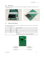
Страница 49: ...can be programmed to operate as an Upstream slot or Downstream slot 16 2 Slot LEDs Item Name Description When Lit Solid Green or Blinking When Off 1 Target Slot LED Upstream Slot LED Solid Gen4 Link OFF Not Linked No Card present in the slot Blink 2Hz Gen3 Link Blink 1Hz Gen2 Link Blink 0 5Hz Gen1 Link Slow Blinking 2 Downstream LED PCIe slot LEDs Solid Gen4 Link OFF Not Linked No Card present in ...

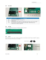
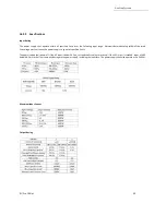
Страница 50: ...pause counts 8 blinks D10 Config output from the FPGA but enabled as an FPGA option When RED board is not programmed OFF board is programmed 16 4 Slot Type Slot Type Closed ended PCIe slot connector x16 mechanical and x16 electrical Gen 4 16 5 PS_ON A two pin connector for a shunt jumper which allows the backplane to force power ON when the ATX supply is switched ON See photos below for the locati...

Страница 51: ...apping Each slot on the OSS backplane is mapped to a PCIe port on the 88096 PCIe switch Port mapping is hard coded it is essentially fixed No means of changing or modifying it Port Slot Slot Mapping 88096 Port Slot 0 0 Slot 1 48 Slot 2 64 Slot 3 80 Slot 4 32 Slot 5 16 Daisy chain If slot 5 is cabled to the daisy chain port it becomes port 16 of the 88096 regardless of upstream downstream configura...

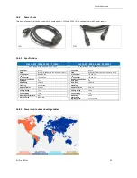
Страница 52: ... 5 15P 2ND Connector IEC 320 C13 Number of Conductors 3 Cord Type SJT Wire Gauge 14 AWG Shielding Unshielded Approval Marks CSA UL Approved Countries Canada USA Voltage Rating 125V Current Rating 15A Operating Temperature 60 C Digi Key Part Q944 ND Part Status Active Style Male pins Blades to Female Sockets slots 1st Connector IEC 320 C14 2ND Connector IEC 320 C13 Number of Conductors 3 Cord Type ...

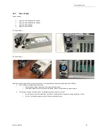
Страница 53: ...C power supply modules ea 1600 W With two power supply modules installed o Share the power load requirements during normal operations o Should one module fail for any reason the power load will be shifted to the other module LED indicator to keep you informed on normal abnormal conditions for your PSU o An indicator for the failure would be the LEDs on the back panel of the power supply behind the...

Страница 54: ...Slot 54 16 9 1 Removing AC Power Supply 1 Disconnect the power cord from the power supply you are removing 2 Grasp the power supply handle 3 Press the black release latch upward and hold it 4 Pull the power supply out of the bay ...

Страница 55: ...0psec duration 128 3A 178 3A MIN LOAD 0A 0A VOLTAGE REGULATION 5 5 RIPPLE NOISE 120mV 120mV Max Capacitive Loads 50000uF 3100uF Min Capacitive Loads 2000uF 10uF Dynamic Load Capacitive Load 2000uF 20uF One Stop Systems 4U Pro 10 Slot 55 16 9 2 Specifications Input Rating The power supply shall operate within all specified limits over the following input range Harmonic distortions of up to10 of the...

Страница 56: ...Requirements Specification AC cord unplugged or AC power lost with a AMBER second power supply in parallel still with AC input power Power supply critical event causing a AMBER shutdown failure over current short circuit over voltage fan failure over temperature Power supply warning events where the power 1Hz Blink supply continues to operate high temp high Amber power high current slow fan Power ...

Страница 57: ...ature Weight gram g Current Rating Voltage Rating Material Frame Material Blade Lifetime Temp 44 40W 11500RPM 4 Wire Leads 10 70 C 260g 3 70A 07 0 13 2VDC Plastic 70000 Hrs 40C One Stop Systems 4U Pro 10 Slot 57 16 10 Fan The expansion unit has two fans installed with sufficient capacity to provide cooling to the extreme high heat generating GPUs These are high CFM RPM replaceable fans The fans ha...

Страница 58: ...an Loose n the thumbscrew and slowly pull the fan out see photos below 16 11 Fan Foam Air Filter The 4UP can be configured to come with fan foam air filters with minimal airflow resistance to prevent dust from entering the expansion unit You can easily remove and clean the filter To access the foam air filter simply remove the fan first and pull the filter out see photos below ...

Страница 59: ...ion Connector of Connector 8 pin 290 010 037 RC 01 Cable Assy Aux Pwr 8 Pin NVIDIA 2 0 12 Expansion System M176 OSS 8 pin male to 8 pin male One 8 pin connector 290 010 037 RC 02 Cable Assy Aux Pwr 8 Pin NVIDIA 2 0 24 Expansion System M176 OSS 8 pin male to 8 pin male One 8 pin connector 6 2 pin 290 010 013 RC Cable Assy Canister External Pwr Dual 6 2 PCIe Graphics Only 8 pin male to 2 6 2 pin mal...

Страница 60: ... directly from the power supply backplane and there are 10 available AUX power connections ports in which the auxiliary power cables are plugged in see photo below To plug in the 6 2 pin cable correctly connect the Y end connector of the cable to the power distribution board see photos below To plug in the 8 pin cable correctly you can use either X or Y end of the cable see photos below ...

Страница 61: ...o 10 Slot 61 Ensure the cable is fully seated and secured NOTE Route cables away from FANs For safety and proper airflow avoid blocking the fans 16 12 2 Pin Outs PSU board aux port pin outs 8 pin aux power cable and pin outs ...

Страница 62: ...Figure A1 Figure A2 One Stop Systems 4U Pro 10 Slot 62 6 2 pin aux power cable and pin outs ...

Страница 63: ...ch the aux power cable A PCIe slot provides 75 watts of slot power which is not enough to meet the power requirement for a high end add in card with power consumption A direct connection to the power system is needed to obtain additional power This can be done by using the 6 2 pin or 8 pin auxiliary power cables The below photos represent how the 6 2 pin connector and 8 pin aux power cables are at...

Страница 64: ...ower connectors PCI Express x16 Graphics 150 W ATX Specification Published in October 2004 this standard defines a six pin 2x3 auxiliary power connector capable of delivering an additional 75 W to a graphics card directly from the power supply for a total of 150 W to the card PCI Express 225 W 300 W High Power Card Electromechanical Specification Published in March 2008 this standard defines an ei...

Страница 65: ...from 6 pin 150 Watt from 8 pin Figure B shows the wrong power cable to use due to special keying on the eight pin connector The GPU power connector has a different keying to prevent interchanging with the 12 V power connectors NOTE We do not provide different aux power cables i e 8pin to 4pin Molex other than what we offer If your PCIe card requires a different power adapter or aux power cable you...

Страница 66: ...oot the system after installing the driver 17 3 No link between host and target cards 1 Check the dipswitches on each card Make sure the Target card is set to target mode and Host card is set to host mode 2 Check the Target card is installed in the target slot upstream slot 3 Use a validated certified OSS HIB Cable adapter Gen4 cards 4 Reseat the Cables Makes sure you are using a Gen4 cables 5 Swa...

Страница 67: ...s in should be removed or not to be installed prior to shipment to avoid or prevent possible damage Note Expansion board and PCIe PCI cards that arrive damaged in shipment will not be covered under warranty 18 2 Returning Merchandise If factory service is required a Service Representative will give you a Return Merchandise Authorization RMA number Put this number and your return address on the shi...

Страница 68: ...d identifying if any technical issue may be related to third party hardware or software In order to isolate technical issues OSS may request that the system be returned to the same configuration that shipped from the OSS factory and any non OSS supplied third party hardware or software be removed from the system during troubleshooting We test certify and support many third party hardware and softw...

Страница 69: ...One Stop Systems 4U Pro 10 Slot 69 ...

Отзывы: