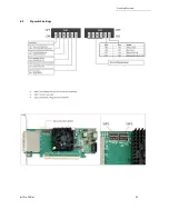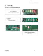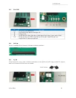
LED
Status
CHO
D1
ON (Solid Green)
LED0
D2
ON (Solid Green)
LED1
D4
ON (Solid Green)
LED2
D6
ON (Solid Green)
LED3
D8
ON (Solid Green)
CE
D11
ON (Solid Green)
Description
link LED. Indicates a connectivity between OSS Host and Target
cards.
Power Good
Power Good
Power Good
Power Good
Solid Green: The CARD EDGE connector is communicating to Gen4
PCIe switch on the host computer motherboard.
Blinking Green: The CARD EDGE connector is communicating to
Gen3 PCIe switch on the expansion board / backplane
Power Good / FPGA Healthy
AUX Power Good
PWR
D10
ON (Blinking Green)
AUX
D9
ON (Solid Green)
One Stop Systems
4U Pro 10 Slot
36
11.4
Adapter Card LED Definitions
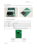
LEDs for SFF-8644 Cable Link cases:
1.
Target mode (x16): D1 is the link indicator
2.
Host Mode, x16: D1 is the link indicator
3.
Host Mode, x8x8: D1 or D5 are the link indicators (one for each corresponding group of two SFF cages)
4.
Host Mode, x4x4x4x4: D1, D3, D5, D7 are the link indictors (one for each SFF cage)
11.5
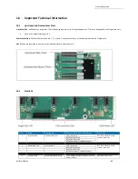
Slot LEDs
•
The SLOT LEDs will illuminate either Solid green or blinking if a PCIe card is occupying the slot.
•
The Target SLOT LED will illuminate as solid green.
Solid
Gen4 Link
Blink 2Hz
Gen3 Link
Blink 1Hz
Gen2 Link
Blink 0.5Hz
Gen1 Link (Slow Blinking)
OFF
No card installed
Содержание 4UP 10-SLOT GEN4
Страница 1: ...INSTALLATION GUIDE 4UP 10 SLOT GEN4 4UP 10 SLOT Gen4 www onestopsystems com ...
Страница 8: ...One Stop Systems 4U Pro 10 Slot 8 1 5 Dimensions ...
Страница 62: ...Figure A1 Figure A2 One Stop Systems 4U Pro 10 Slot 62 6 2 pin aux power cable and pin outs ...
Страница 69: ...One Stop Systems 4U Pro 10 Slot 69 ...

