SECTION 6 - JLG CONTROL SYSTEM
6-6
– JLG Lift –
3121827
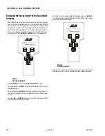
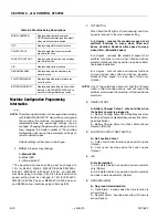
The effect of the machine digit value is displayed along
with its value. The above display would be selected if the
machine was equipped with a ground alarm and you
wanted it to sound when driving. There are certain set-
tings allowed to install optional features or select the
machine model.
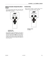
When selection the machine model to match the size of
the machine, the personality settings will all default to the
factory recommended setting.
NOTE:
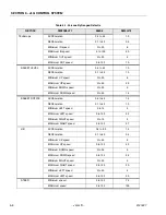
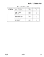
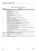
Refer to Table 6-1, Personality Ranges/Defaults, and
Table 6-2, Machine Setup Descriptions in this Ser-
vice Manual for the recommended factory settings.
NOTE:
Password 33271 will give you access to level 1,
which will permit you to change all machine person-
ality settings.
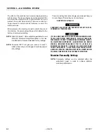
There is a setting that JLG strongly recommends that you
do not change. This setting is so noted below:
ELEVATION CUTBACK
CHANGING THis SETTING MAY ADVERSELY AFFECT THE PER-
FORMANCE OF YOUR MACHINE.
ITS IS A GOOD PRACTICE TO AVOID PRESSURE-WASHING ELEC-
TRICAL/ELECTRONIC COMPONENTS. SHOULD PRESSURE-
WASHING BE UTILIZED TO WASH AREAS CONTAINING ELECTRI-
CAL/ELECTRONIC COMPONENTS, JLG INDUSTRIES INC. RECOM-
MENDS A MAXIMUM PRESSURE OF 750 PSI (52 BAR) AT A
MINIMUM DISTANCE OF 12 INCHES (30.5CM) AWAY FROM
THESE COMPONENTS. IF ELECTRICAL/ELECTRONIC COMPO-
NENTS ARE SPRAYED, SPRAYING MUST NOT BE DIRECT AND BE
FOR BRIEF TIME PERIODS TO AVOID HEAVY SATURATION.
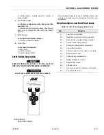
Machine Personality Settings
NOTE:
Personality settings can be adjusted within the
adjustment range in order to achieve optimum
machine performance.
Содержание JLG E400AJP
Страница 2: ......
Страница 21: ...SECTION 1 SPECIFICATIONS 3121827 JLG Lift 1 7 Figure 1 2 Operator Maintenance Lubrication Diagram...
Страница 32: ...SECTION 1 SPECIFICATIONS 1 18 JLG Lift 3121827 NOTES...
Страница 42: ...SECTION 2 GENERAL 2 10 JLG Lift 3121827 NOTES...
Страница 54: ...SECTION 3 CHASSIS TURNTABLE 3 12 JLG Lift 3121827 Figure 3 3 Speed Sensor Orientation...
Страница 55: ...SECTION 3 CHASSIS TURNTABLE 3121827 JLG Lift 3 13 Figure 3 4 Frame Mounted Electrical Components Sheet 1 of 2...
Страница 56: ...SECTION 3 CHASSIS TURNTABLE 3 14 JLG Lift 3121827 Figure 3 5 Frame Mounted Electrical Components Sheet 2 of 2...
Страница 60: ...SECTION 3 CHASSIS TURNTABLE 3 18 JLG Lift 3121827 Figure 3 7 Steering Components and Spindles...
Страница 62: ...SECTION 3 CHASSIS TURNTABLE 3 20 JLG Lift 3121827 Figure 3 9 Tilt Sensor Location...
Страница 86: ...SECTION 3 CHASSIS TURNTABLE 3 44 JLG Lift 3121827 Figure 3 16 Swing Components...
Страница 88: ...SECTION 3 CHASSIS TURNTABLE 3 46 JLG Lift 3121827 Figure 3 18 Battery Cable Connections...
Страница 90: ...SECTION 3 CHASSIS TURNTABLE 3 48 JLG Lift 3121827 Figure 3 20 On Board Generator...
Страница 97: ...SECTION 3 CHASSIS TURNTABLE 3121827 JLG Lift 3 55 Figure 3 22 Generator Components...
Страница 100: ...SECTION 3 CHASSIS TURNTABLE 3 58 JLG Lift 3121827 Figure 3 23 Generator System Analyzer Flow Chart...
Страница 116: ...SECTION 3 CHASSIS TURNTABLE 3 74 JLG Lift 3121827 NOTES...
Страница 125: ...SECTION 4 BOOM PLATFORM 3121827 JLG Lift 4 9 Figure 4 8 Jib Platform Components and Attaching Hardware...
Страница 127: ...SECTION 4 BOOM PLATFORM 3121827 JLG Lift 4 11 Figure 4 10 Boom Limit Switches...
Страница 140: ...SECTION 4 BOOM PLATFORM 4 24 JLG Lift 3121827 Figure 4 13 Rotator Counterbalance Valve...
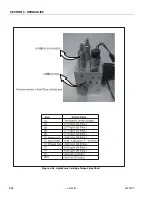
Страница 178: ...SECTION 5 HYDRAULICS 5 24 JLG Lift 3121827 Figure 5 26 HydraForce Cartridge Torque Value Chart...
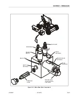
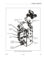
Страница 179: ...SECTION 5 HYDRAULICS 3121827 JLG Lift 5 25 Figure 5 27 Main Valve Components Prior to S N 62642...
Страница 214: ...SECTION 6 JLG CONTROL SYSTEM 6 34 JLG Lift 3121827 NOTES...
Страница 257: ......

