SECTION 4 - BOOM & PLATFORM
3121827
– JLG Lift –
4-7
6.
Carefully install the telescope cylinder barrel end to
base, securing cylinder to the base boom with four
(4) bolts and hardware.
7.
Remove applicable hydraulic line and port caps and
correctly connect the hydraulic lines to the tele-
scope cylinder. Ensure all hoses are correctly
routed.
8.
Remove boom prop and overhead crane. Activate
hydraulic system.
9.
Using all applicable safety precautions, operate the
boom functions. Check for correct operation and
hydraulic leaks. Secure as necessary.
10.
Check fluid level of hydraulic tank and add as neces-
sary.
4.6 MID AND LOWER LIFT CYLINDER
BLEEDING PROCEDURE
NOTE:
Bleeding procedure should only be necessary if
rebuilding or replacing lift cylinder.
1.
Check oil level in the hydraulic oil tank (all booms
must be retracted).
2.
Lay an oil drip pan under the rod end port block
(Mid Cylinder) and crack bleeder open from the fit-
ting in the port block.
3.
From the platform, turn the speed control knob to
the slow position.
4.
Lift up very slowly. This will force any air out of the
circuit. If the lower boom is not extending, turn the
speed control up very slowly until the lower boom
starts to move.
5.
Raise the lower boom approximately. 30.5 cm (1
foot), then close bleeder while the boom is still mov-
ing.
6.
Lift down all the way.
7.
Repeat this procedure until all air has been purged
from the circuit. Re-check the hydraulic oil level.
8.
To test, cycle the lower lift function 3-4 times to see if
both cylinders stop at the same time when fully
extended.
4.7 WEAR PADS
1.
Shim up wear pads until snug to adjacent surface.
2.
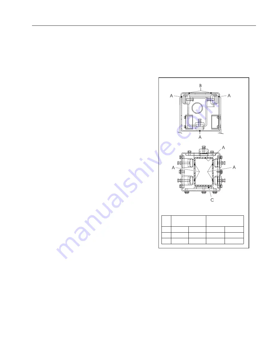
Replace wear pads when worn to thickness shown
below
.
3.
Adjust wear pads as follows:
a.
Loosen jam nut on adjustment bolt, turn bolt CW
until wear pad is snug to adjacent surface.
b.
After adjustments have been made, tighten the
jam nuts on wear pad bolts.
Figure 4-6. Wear Pad Thickness
Table 4-1.Wear Pad Thickness
Pad
Thickness of
New Pad
Replace When Worn to:
A
0.75"
19 mm
0.375"
9.5 mm
B
0.5"
13 mm
0.3125"
8 mm
C
0.5"
13 mm
0.3125"
8 mm
Содержание JLG E400AJP
Страница 2: ......
Страница 21: ...SECTION 1 SPECIFICATIONS 3121827 JLG Lift 1 7 Figure 1 2 Operator Maintenance Lubrication Diagram...
Страница 32: ...SECTION 1 SPECIFICATIONS 1 18 JLG Lift 3121827 NOTES...
Страница 42: ...SECTION 2 GENERAL 2 10 JLG Lift 3121827 NOTES...
Страница 54: ...SECTION 3 CHASSIS TURNTABLE 3 12 JLG Lift 3121827 Figure 3 3 Speed Sensor Orientation...
Страница 55: ...SECTION 3 CHASSIS TURNTABLE 3121827 JLG Lift 3 13 Figure 3 4 Frame Mounted Electrical Components Sheet 1 of 2...
Страница 56: ...SECTION 3 CHASSIS TURNTABLE 3 14 JLG Lift 3121827 Figure 3 5 Frame Mounted Electrical Components Sheet 2 of 2...
Страница 60: ...SECTION 3 CHASSIS TURNTABLE 3 18 JLG Lift 3121827 Figure 3 7 Steering Components and Spindles...
Страница 62: ...SECTION 3 CHASSIS TURNTABLE 3 20 JLG Lift 3121827 Figure 3 9 Tilt Sensor Location...
Страница 86: ...SECTION 3 CHASSIS TURNTABLE 3 44 JLG Lift 3121827 Figure 3 16 Swing Components...
Страница 88: ...SECTION 3 CHASSIS TURNTABLE 3 46 JLG Lift 3121827 Figure 3 18 Battery Cable Connections...
Страница 90: ...SECTION 3 CHASSIS TURNTABLE 3 48 JLG Lift 3121827 Figure 3 20 On Board Generator...
Страница 97: ...SECTION 3 CHASSIS TURNTABLE 3121827 JLG Lift 3 55 Figure 3 22 Generator Components...
Страница 100: ...SECTION 3 CHASSIS TURNTABLE 3 58 JLG Lift 3121827 Figure 3 23 Generator System Analyzer Flow Chart...
Страница 116: ...SECTION 3 CHASSIS TURNTABLE 3 74 JLG Lift 3121827 NOTES...
Страница 125: ...SECTION 4 BOOM PLATFORM 3121827 JLG Lift 4 9 Figure 4 8 Jib Platform Components and Attaching Hardware...
Страница 127: ...SECTION 4 BOOM PLATFORM 3121827 JLG Lift 4 11 Figure 4 10 Boom Limit Switches...
Страница 140: ...SECTION 4 BOOM PLATFORM 4 24 JLG Lift 3121827 Figure 4 13 Rotator Counterbalance Valve...
Страница 178: ...SECTION 5 HYDRAULICS 5 24 JLG Lift 3121827 Figure 5 26 HydraForce Cartridge Torque Value Chart...
Страница 179: ...SECTION 5 HYDRAULICS 3121827 JLG Lift 5 25 Figure 5 27 Main Valve Components Prior to S N 62642...
Страница 214: ...SECTION 6 JLG CONTROL SYSTEM 6 34 JLG Lift 3121827 NOTES...
Страница 257: ......


