background image

© 2008 Directed Electronics.  All rights reserved. 


                          GXTR102 2008-10

Vista, CA 92081

w w w. d i r e c t e d . c o m

directed electronics is committed to delivering 
world  class  quality  products  and  services 
that excite and delight our customers.

Directed Electronics is an 

ISO 9001 registered company.

WARRANTY

LIMITED ONE-YEAR CONSUMER WARRANTY/*LIMITED TWO-YEAR CONSUMER WARRANTY FOR AUTHORIZED 
DIRECTED DEALER PURCHASE & INSTALLATION

Directed Electronics (herein “Directed”) promises to the original purchaser of the subwoofer or amplifier, as 
applicable (herein “Unit” or “Product”), to repair or replace with a new or refurbished Unit (at Directed’s sole 
and absolute discretion) should the Unit prove to be defective in workmanship or material under normal use, 
for a period of *two-years from the date of purchase from the authorized Directed dealer PROVIDED the Unit 
was purchased and installed by an authorized Directed dealer. During this *two-year period, there will be no 
charge for the repair or replacement PROVIDED the Unit is returned to Directed (DO NOT RETURN THE ENTIRE 
ENCLOSURE.  PLEASE RETURN THE WARRANTIED UNIT ONLY.), shipping prepaid, along with the required proof 
of installation, the bill of sale or other dated proof of purchase, and the consumer’s contact information. If 
the Unit is installed by anyone other than an authorized Directed dealer, the warranty period will be one-year 
from the date of purchase. This warranty is non-transferable and does not apply to any Unit that has been 
modified or used in a manner contrary to its intended purpose, and does not cover damage to the Unit caused 
by installation or removal of the Unit. During this one-year period, there will be no charge for the repair or 
replacement PROVIDED the Unit is returned to Directed, shipping pre-paid, along with the bill of sale or other 
dated  proof  of  purchase  and  the  consumer’s  contact  information.  This  warranty  is  void  if  the  product  has 
been damaged by accident or unreasonable use, neglect, improper service or other causes not arising out of 
defects in materials or construction. This warranty does not cover the elimination of externally generated static 
or noise, or the correction of antenna problems or weak reception, damage to speakers, accessories, electri-
cal systems, cosmetic damage or damage due to negligence, misuse, failure to follow operating instructions, 
accidental spills or customer applied cleaners, damage due to environmental causes such as floods, airborne 
fallout, chemicals, salt, hail, lightning or extreme temperatures, damage due to accidents, road hazards, fire, 
theft, loss or vandalism, damage due to improper connection to equipment of another manufacturer, modifi-
cation of existing equipment, or Product which has been opened or tampered for any reason. Units which are 
found to be damaged by abuse resulting in thermally damaged voice coils are not covered by this warranty 
but may be replaced at the absolute and sole discretion of Directed. Unit must be returned to Directed (DO 
NOT RETURN THE ENTIRE ENCLOSURE.  THE UNIT ENCLOSURE IS COVERED BY A SEPARATE 90-DAY LIMITED 
CONSUMER WARRANTY.  PLEASE ONLY RETURN THE WARRANTIED UNIT UNLESS A WARRANTY CLAIM IS BE-
ING MADE FOR THE ENCLOSURE.), postage pre-paid, with bill of sale or other dated proof of purchase bearing 
the following information: consumer’s name, telephone number, and address, authorized dealer’s name and 
address, and product description. Unit must be returned to the following address: ATTN: WARRANTY DEPART-
MENT, Directed Electronics , 1 Viper Way, Vista, CA 92081. Note: This warranty does not cover labor costs for 
the removal and/or reinstallation of the Unit. IN ORDER FOR THE TWO-YEAR WARRANTY TO BE VALID, YOUR 
UNIT MUST BE SHIPPED WITH PROOF OF INSTALLATION BY AN AUTHORIZED DIRECTED DEALER. ALL UNITS 
RECEIVED BY DIRECTED FOR WARRANTY REPAIR WITHOUT PROOF OF DIRECTED DEALER INSTALLATION AND 
PURCHASE WILL BE COVERED BY THE LIMITED 1 YEAR WARRANTY. 

BY PURCHASING THIS PRODUCT, ALL WARRANTIES INCLUDING BUT NOT LIMITED TO EXPRESS WARRANTY, IM-
PLIED WARRANTY, WARRANTY OF MERCHANTABILITY, FITNESS FOR PARTICULAR PURPOSE, AND WARRANTY 
OF NON-INFRINGEMENT OF INTELLECTUAL PROPERTY ARE EXPRESSLY EXCLUDED TO THE MAXIMUM EXTENT 
ALLOWED BY LAW, AND DIRECTED NEITHER ASSUMES NOR AUTHORIZES ANY PERSON TO ASSUME FOR IT ANY 
LIABILITY IN CONNECTION WITH THE SALE OF THE PRODUCT. DIRECTED HAS ABSOLUTELY NO LIABILITY FOR 
ANY AND ALL ACTS OF THIRD PARTIES INCLUDING ITS AUTHORIZED DEALERS OR INSTALLERS. IN NO EVENT 
WILL DIRECTED BE LIABLE FOR ANY INCIDENTAL, SPECIAL OR CONSEQUENTIAL DAMAGES (INCLUDING LOSS 
OF PROFITS). BY PURCHASING THIS PRODUCT, THE CONSUMER AGREES AND CONSENTS THAT ALL DISPUTES 
BETWEEN THE CONSUMER AND DIRECTED SHALL BE RESOLVED IN ACCORDANCE WITH CALIFORNIA LAWS IN 
SAN DIEGO COUNTY, CALIFORNIA. This warranty is only valid for sale of Product within the United States of 
America. Product sold outside of the United States of America is sold “AS-IS,” and shall have NO WARRANTY, 
express or implied. Some states do not allow limitation on how long an implied warranty lasts. In such states, 
the limitation or exclusions of this Limited Warranty may not apply. Some states do not allow the exclusion 
or limitation of incidental or consequential damages. In such states, the exclusion or limitation of this Limited 
Warranty may not apply to you. This Limited Warranty gives you specific legal rights, and you may have other 
rights which vary from state to state. 


          920-0033 04-07

For more information on Orion products please visit www.orioncaraudio.com

Содержание XTR102

Страница 1: ...Subwoofer MODEL XTR102 XTR104 XTR122 XTR124 XTR152 XTR154 OWNER S MANUAL...

Страница 2: ...t give you with the manual is personal installation or technical experience If you have questions concerning the use or application of this product please refer to the nearest Orion dealer for assista...

Страница 3: ...ers is directly proportional to the quality of the installation Care taken with the installation process will be rewarded by years of satisfying performance If you are unsure of your installation abil...

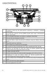
Страница 4: ...il former 2 5 voice coil former 6 8mm steel front plate 7 Large 2 stack ceramic magnets Large single magnet on 10 models 8 8mm steel back plate pole piece T yoke assembly 9 1 125 vent Part of the enha...

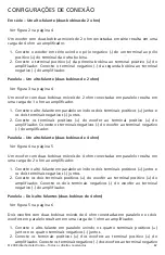
Страница 5: ...e first coil to the positive terminal on the amplifier Wire the negative terminal of the second coil to the negative terminal on the amplifier Parallel One Speaker dual 2 ohm voice coils One dual 2 oh...

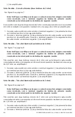
Страница 6: ...ohm load to the amplifier 4 ohm 4 ohm Figure 4 Figura 4 Abbildung 4 _ _ _ 1 Connect the speaker in parallel by connecting the two positive terminals together and the two negative terminals together 2...

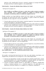
Страница 7: ...ults in a 1 ohm load to the amplifier 4 ohm 4 ohm 4 ohm 4 ohm Figure 5 Figura 5 Abbildung 5 1 Connect the speaker in parallel by connecting the four positive terminals together and the four negative t...

Страница 8: ...ce coil woofers with voice coils in series and then parallel the two series woofers results in a 2 ohm load to the amplifier 2 ohm 2 ohm 2 ohm 2 ohm Figure 6 Figura 6 Abbildung 6 1 Connect each woofer...

Страница 9: ...ofer with voice coils of each woofer wired in series and then parallel the three woofers for a resulting 2 67 ohm load to the amplifier 4 ohm 4 ohm 4 ohm 4 ohm 4 ohm 4 ohm Figure 7 Figura 7 Abbildung...

Страница 10: ...ofer with voice coils of each woofer wired in series and then parallel the three woofers for a resulting 1 33 ohm load to the amplifier 2 ohm 2 ohm 2 ohm 2 ohm 2 ohm 2 ohm Figure 8 Figura 8 Abbildung...

Страница 11: ...red with the voice coils on each woofer in series and then parallel the four woofers for a resulting 2 ohm load to the amplifier 4 ohm 4 ohm 4 ohm 4 ohm 4 ohm 4 ohm 4 ohm 4 ohm Figure 9 Figura 9 Abbil...

Страница 12: ...ed with the voice coils on each woofer in series and then parallel the four woofers for a resulting 1 ohm load to the amplifier 2 ohm 2 ohm 2 ohm 2 ohm 2 ohm 2 ohm 2 ohm 2 ohm Figure 10 Figura 10 Abbi...

Страница 13: ...ung 11 1 Connect one of the speaker s voice coils to the first amplifier by connecting the positive terminal and the negative terminal from the speaker to the respective positive terminal and the nega...

Страница 14: ...ung 12 1 Connect one of the speaker s voice coils to the first amplifier by connecting the positive terminal and the negative terminal from the speaker to the respective positive terminal and the nega...

Страница 15: ...93 Cms mechanical compliance mm N 0 348 0 310 0 311 Bl motor strength Tesla M 12 18 16 51 13 86 Sd effective radiating area sq cm 283 529 283 529 433 736 Sd effective radiating area sq in 43 964 43 96...

Страница 16: ...4 Cms mechanical compliance mm N 0 278 0 203 0 185 Bl motor strength Tesla M 18 90 14 36 18 14 Sd effective radiating area sq cm 433 736 779 311 779 311 Sd effective radiating area sq in 67 255 120 83...

Страница 17: ...stem Energy Bandwidth Product EBP is determined by the following formula Fs Qes EBP EBP values of 50 and lower suggest a sealed enclosure is best 50 to90 means the subwoofers versatile and 90 and abov...

Страница 18: ...A vented enclosure will offer greater efficiency and stronger low bass output compared to a sealed design A vented enclosure uses the back wave sound from the back side of the cone to reinforce the o...

Страница 19: ...16 in 360 mm width b 13 5 in 343 mm thickness 0 75 in 19 mm 1 Front 1 Back height a 12 in 305 mm width d 12 in 305 mm thickness 0 75 in 19 mm 2 Sides height a 12 in 305 mm depth c 14 16 in 360 mm thi...

Страница 20: ...Parts 1 Duct outside diameter e 3 25 in 83 mm inside diameter g 3 in 76 mm length h 9 879 in 251 mm c b Top Bottom a d Front Back c Sides h g A B C External Dimensions A 12 in 305 mm B 15 5 in 394 mm...

Страница 21: ...ht a 14 5 in 368 mm depth c 14 66 372 mm thickness 0 75 in 19 mm Driver Mounting Mounting Front Top Bottom a d Front Back c Sides A B C External Dimensions A 16 in 406 mm B 16 in 406 mm C 14 66 in 372...

Страница 22: ...1 Duct outside diameter e 4 25 in 108 mm inside diameter g 4 in 102 mm length h 11 26 in 286 mm c b Top Bottom a d Front Back c Sides A B C External Dimensions A 13 5 in 343 mm B 18 5 in 470 mm C 15...

Страница 23: ...t a 16 in 406 mm depth c 16 23 in 412 mm thickness 0 75 in 19 mm Driver Mounting Mounting Front Top Bottom a d Front Back c Sides A B C External Dimensions A 17 5 in 445 mm B 17 5 in 445 mm C 16 23 in...

Страница 24: ...Square 1 Duct outside diameter e 4 25 in 108 mm inside diameter g 4 in 102 mm length h 5 422 in 138 mm c b Top Bottom a d Front Back c Sides A B C External Dimensions A 18 5 in 470 mm B 23 5 in 597 mm...

Страница 25: ...te la section relative aux caissons clos et aux caissons vent accord avant de commencer l installation CHOIX DES EMPLACEMENTS DE MONTAGE DES HAUT PARLEURS Le choix des emplacements de montage des haut...

Страница 26: ...de bobine mobile de 2 5 6 Plaque avant en acier 8 mm 7 Pile de 2 gros aimants c ramique 8 Plaque arri re en acier 8 mm bloc de pi ce polaire en T 9 vent de 29 mm faisant partie du syst me de refroidi...

Страница 27: ...t parleur de graves la borne positive de l amplificateur Raccordez les bornes n gatives du haut parleur de graves la borne n gative de l amplificateur Parall le Un haut parleur deux bobines mobiles de...

Страница 28: ...s de 4 ohms Voir la figure 7 la page 8 Remarque V rifiez que le c blage du haut parleur de graves est conforme l illustration avec la borne n gative de la premi re bobine du haut parleur de graves rel...

Страница 29: ...la borne n gative de la seconde bobine de chaque haut parleur de graves la borne n gative de l amplificateur S rie parall le Quatre haut parleurs deux bobines mobiles de 2 ohms Voir la figure 10 la p...

Страница 30: ...rrespondantes du premier amplificateur 2 Raccordez l autre bobine mobile du haut parleur au second amplificateur en reliant les bornes positive et n gative du haut parleur aux bornes positive et n gat...

Страница 31: ...t l phoner au service d assistance tech nique audio Panneau de fibres de densit moyenne de 19 mm recommand 2 Les recommandations de caissons indiquent des volumes NETS Les volumes du 3 haut parleur et...

Страница 32: ...e pr cision de reproduction du son Un caisson clos plus petit permet un meilleur contr le ce qui se traduit par des graves plus rapides et plus pr cis Par rapport un mod le clos un caisson vent accord...

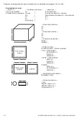
Страница 33: ...v tement int rieur de l enceinte Explication des diagrammes de caissons clos voir les dimensions en pages 18 20 et 22 c b a d c A B C l ments du caisson Forme du caisson prisme carr 1 haut 1 bas profo...

Страница 34: ...geur d paisseur 2 c t s hauteur a profondeur c paisseur Montage du haut parleur Montage Avant Haut et bas Avant et arri re C t s Dimensions externes A B C Dimensions internes A B C paisseur parois Ava...

Страница 35: ...usted mismo lea toda la secci n sobre cajas selladas y ventiladas antes de comenzar la instalaci n UBICACIONES DE MONTAJE DE LOS ALTAVOCES Escoger la ubicaci n correcta de los altavoces tendr un efec...

Страница 36: ...a de 2 5 plg 6 Plancha delantera de acero de 8 mm 7 2 imanes grandes de cer mica de 2 pilas 8 Unidad de yugo en T de pieza polar y plancha trasera de acero de 8 mm 9 Respiradero de 1 125 plg Parte del...

Страница 37: ...woofer a la terminal positiva del amplificador Conecte las terminales negativas del woofer a la terminal negativa del amplificador En paralelo un altavoz dos bobinas ac sticas de 4 Vea la figura 4 en...

Страница 38: ...positiva de la bobina del otro woofer Tres woofers con dos bobinas ac sticas de 4 cada uno las bobinas ac sticas en serie y los 3 woofers en paralelo producen una carga de 2 67 en el amplificador 1 C...

Страница 39: ...la bobina de un woofer conectada a la terminal positiva de la bobina del otro woofer Cuatro woofers con dos bobinas ac sticas de 2 cada uno las bobinas ac sticas en serie y los 4 woofers en paralelo...

Страница 40: ...m s detalles Modelo N de pieza XTR Tama o Par metros Thiele Small Fs resonancia al aire libre Hz Vas cumplimiento de equivalencia pies3 Vas cumplimiento de equivalencia litros Qms Q mec nico Qes Q el...

Страница 41: ...g 19mm de grosor 2 Los vol menes de caja recomendados son NETOS El desplazamiento del altavoz y 3 del puerto se incluyen en el volumen de la caja No es necesario agregarlos para calcular el volumen BR...

Страница 42: ...jas selladas peque as dan m s control lo cual se traduce en bajos m s r pidos y precisos Las cajas con ventilaci n tienen m s eficiencia y m s salida de bajos en comparaci n con las selladas La caja v...

Страница 43: ...la caja Traducci n del diagrama de la caja sellada las medidas se encuentran en las p ginas 18 20 y 22 c b a d c A B C Partes de la caja Forma de la caja prisma cuadrado 1 parte de arriba 1 parte de a...

Страница 44: ...ados alto a fondo c grosor Montaje del excitador Montaje adelante Parte de arriba y parte de abajo Parte de adelante y parte de atr s Lados Dimensiones externas A B C Dimensiones internas A B C Grosor...

Страница 45: ...ginn der Installation den gesamten Abschnitt ber geschlossene Geh use und Bassreflexgeh use durchlesen SO PLATZIEREN SIE DIE LAUTSPRECHER Die Wahl der korrekten Lautsprecherposition hat gro e Auswirku...

Страница 46: ...wingspulentr ger 6 8 mm dickes vorderes Abdeckblech 7 Gro e Double Stack Keramikmagneten 8 8 mm dickes hinteres Abdeckblech Polplatten T St ck 9 1 125 Zoll ffnung Teil des verbesserten Schwingspulen K...

Страница 47: ...eiden negativen Terminals miteinander verbinden 2 Verbinden Sie die positiven Terminals des Tieft ners mit dem positiven Terminal am Verst rker Verbinden Sie das negative Terminal des Tieft ners mit d...

Страница 48: ...Lautsprecher doppelte 4 Ohm Schwingspulen Siehe Abbildung 7 auf Seite 8 Hinweis StellenSiesicher dassdieTieft neranschl ssewiegezeigtvorgenommen wurden wobei der negative Anschluss an der ersten Tief...

Страница 49: ...spule mit dem positiven Terminal der zweiten Spule verbinden 2 Verbinden Sie die positiven Terminals der ersten Schwingspule am jeweiligen Tieft ner mit dem positiven Terminal am Verst rker Verbinden...

Страница 50: ...ng 12 auf Seite 13 Ein Tieft ner mit doppelten 4 Ohm Schwingspulen bei dem jede Schwingspule an einen separaten Verst rker angeschlossen ist Lastwiderstand von 4 Ohm am Verst rker 1 Schlie en Sie eine...

Страница 51: ...ohne vorherige Ank ndigung ge ndert werden GEH USEDETAILS Die aufgelisteten Parameter gelten nur f r konventionelle Anwendungen Um 1 weitere Hilfe zu erhalten rufen Sie bitte den Tech Audio Support a...

Страница 52: ...nschen Das kleinere geschlossene Geh use bietet mehr Kontrolle was einen h rbar schnelleren und pr ziseren Bass erm glicht Ein Bassreflexgeh use bietet mehr Leistungsverm gen und einen st rkeren Tiefb...

Страница 53: ...ung der Innenseite des Geh uses n tig Erkl rung des Diagramms f r geschlossene Geh use Ma e finden Sie auf S 18 20 und 22 c b a d c A B C Geh useteile Geh useform Quader 1 Oberseite 1 Unterseite Tiefe...

Страница 54: ...ke 1 Vorderseite 1 R ckseite H he a Breite d Dicke 2 Seiten H he a Tiefe c Dicke Treibereinbau Einbau Vorn Oben und unten Vorn und hinten Seiten Au enma e A B C Innenma e A B C Wandst rke Vorn Seiten...

Страница 55: ...entilate INDIVIDUAZIONE DEI PUNTI DI MONTAGGIO DEGLI ALTOPARLANTI La scelta dei punti di montaggio degli altoparlanti ha la massima influenza sulla qualit del suono dell impianto Nello scegliere la co...

Страница 56: ...a 6 4 cm 6 Piastra anteriore in acciaio da 8 mm 7 Due grandi magneti ceramici in cascata 8 Piastra posteriore in acciaio da 8 mm staffa a T per i poli 9 Apertura da 19 mm Parte del sistema migliorato...

Страница 57: ...terminale positivo dell amplificatore ed entrambi i terminali negativi del woofer al terminale negativo dell amplificatore Un diffusore in parallelo con due bobine mobili da 4 ohm Vedi Figura 4 a pag...

Страница 58: ...seconda bobina mobile del woofer stesso Tre woofer con due bobine mobili da 4 ohm ciascuno collegate in serie applicano un carico di 2 67 ohm all amplificatore quando sono collegati in parallelo 1 Col...

Страница 59: ...bobina mobile del woofer stesso Quattro woofer con due bobine mobili da 2 ohm ciascuno collegate in serie applicano un carico di 1 ohm all amplificatore quando sono collegati in parallelo 1 Collegare...

Страница 60: ...nanza in aria libera Hz Vas volume equivalente di cedevolezza cu ft Vas volume equivalente di cedevolezza litri Qms Q meccanico Qes Q elettrico Qts Q totale driver Re resistenza in c c ohm Z impedenza...

Страница 61: ...er il volume della cassa sono valori NETTI Il volume della cassa 3 tiene conto dei volumi dell altoparlante e dell apertura non occorre aggiungerli per calcolare il volume LORDO della cassa NOTE A cau...

Страница 62: ...ssa pi piccola sigillata offre un controllo superiore che assicura bassi pi veloci e precisi Una cassa ventilata offre efficienza maggiore e un uscita ai bassi estremi pi forte rispetto a una cassa si...

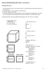
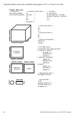
Страница 63: ...la cassa Legenda relativa alla cassa sigillata vedi pagine 18 20 e 22 per le misure c b a d c A B C Parti della cassa Forma della cassa prisma quadrato 1 superiore 1 inferiore profondit c larghezza b...

Страница 64: ...e 2 laterali altezza a profondit c spessore Montaggio del driver Montaggio anteriore Superiore e inferiore Anteriore e posteriore Laterali Dimensioni esterne A B C Dimensioni interne A B C Spessore de...

Страница 65: ...obre caixas ac sticas seladas e ventiladas antes de come ar a instala o DETERMINA O DOS LOCAIS DE INSTALA O DOS ALTOS FALANTES A sele o dos locais corretos para instala o dos alto falantes o fator que...

Страница 66: ...de bobina m vel de 2 5 6 Placa frontal de a o de 8 mm 7 m s cer micos grandes de duas camadas 8 Conjunto de placa traseira haste em T tipo forquilha de 8 mm de a o 9 Abertura de ventila o de 28 6 mm P...

Страница 67: ...o woofer ao terminal positivo do amplificador Conecte os terminais negativos do woofer ao terminal negativo do amplificador Paralela Um alto falante duas bobinas de 4 ohm Ver figura 4 na p gina 5 Um w...

Страница 68: ...do primeiro woofer conectado ao terminal positivo da bobina do segundo woofer Tr s woofers com duas bobinas m veis de 4 ohm com as bobinas de cada woofer conectadas em s rie e em seguida os tr s woofe...

Страница 69: ...dos woofers estejam conectados como mostrado com o terminal negativo da bobina do primeiro woofer conectado ao terminal positivo da bobina do segundo woofer Quatro woofers com duas bobinas m veis de 2...

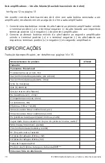
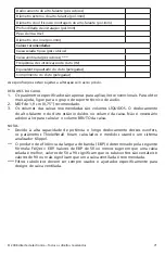
Страница 70: ...s positivo e negativo do segundo amplificador ESPECIFICA ES Tradu o das especifica es ver detalhes nas p ginas 14 e 15 Modelo N mero do produto XTR Tamanho Par metros Thiele Small Fs resson ncia ao ar...

Страница 71: ...o grupo de suporte t cnico de udio MDF de 1 9 cm 0 75 recomendado 2 Os volumes das caixas recomendadas s o volumes L QUIDOS O deslocamento 3 do alto falante e do duto est o inclu dos no volume da cai...

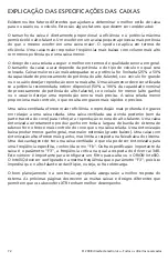
Страница 72: ...rio desejar uma reprodu o sonora mais precisa A caixa selada menor proporciona mais controle o que resulta em graves mais r pidos e precisos Uma caixa ventilada oferece maior efici ncia e reprodu o m...

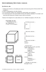
Страница 73: ...aixa Tradu o do diagrama da caixa selada ver as medidas nas p ginas 18 20 e 22 c b a d c A B C Partes da caixa Formato da caixa Prisma quadrada 1 topo 1 parte inferior profundidade c largura b espessu...

Страница 74: ...erais altura a profundidade c espessura Montagem do alto falante Montagem Frente Topo e parte inferior Frente e parte posterior Laterais Dimens es externas A B C Dimens es internas A B C Espessura da...

Страница 75: ...rer modifi cation of existing equipment or Product which has been opened or tampered for any reason Units which are found to be damaged by abuse resulting in thermally damaged voice coils are not cove...

Отзывы: