background image


RDS-3086/3166G  User  Manual 


ORing Industrial Networking Corp


3.2  Wiring 


3.2.1 

Power Inputs 

The device is powered by AC power. Simply insert the AC power cable to the power connector 

at the back of the device and turn on the power switch. The input voltage is 100V~240V / 

50~60Hz. 

3.3  Connection 

3.3.1 

Ethernet Port Pin Assignment 

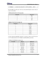
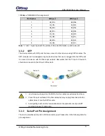
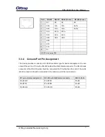
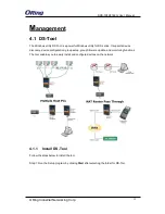
The  device  is  equipped  with  standard  Ethernet  ports.  According  to  the  link  type,  the  device 

uses  CAT  3,  4,  5,5e  UTP  cables  to  connect  to  any  other  network  devices  (PCs,  servers, 

switches, routers, or hubs). Please refer to the following table for cable specifications. 


Cable Types and Specifications: 

Cable 

Type 

Max. Length 

Connector 

10BASE-T 

Cat. 3, 4, 5 100-ohm 

UTP 100 m (328 ft) 

RJ-45 

100BASE-TX 

Cat. 5 100-ohm UTP 

UTP 100 m (328 ft) 

RJ-45 

ATTENTION 

1.  Be sure to disconnect the power cord before installing and/or wiring your 

devices.   

2.  Calculate the maximum possible current in each power wire and 

common wire. Observe all electrical codes dictating the maximum 
current allowable for each wire size.   

3.  If the current goes above the maximum ratings, the wiring could 

overheat, causing serious damage to your equipment. 

4.  Use separate paths to route wiring for power and devices. If power wiring 

and device wiring paths must cross, make sure the wires are 
perpendicular at the intersection point.   

5.  Do not run signal or communications wiring and power wiring through the 

same wire conduit. To avoid interference, wires with different signal 
characteristics should be routed separately.   

6.  You can use the type of signal transmitted through a wire to determine 

which wires should be kept separate. The rule of thumb is that wiring 
sharing similar electrical characteristics can be bundled together   

7.  You should separate input wiring from output wiring   
8.  It is advised to label the wiring to all devices in the system 

WARNING 

Do not disconnect modules or wires unless power has been switched off or 
the area is known to be non-hazardous. The devices may only be connected 
to the supply voltage shown on the type plate. 

Содержание RDS-3086

Страница 1: ...ay y I In nd du us st tr ri ia al l 8 8 1 16 6 p po or rt t S Se er ri ia al l t to o E Et th he er rn ne et t D De ev vi ic ce e S Se er rv ve er r U Us se er r M Ma an nu ua al l V Ve er rs si io on...

Страница 2: ...nses apportioned by ORing and the distributor This warranty does not cover product modifications or repairs done by persons other than ORing approved personnel and this warranty does not apply to ORin...

Страница 3: ...lation 7 3 2 Wiring 8 3 2 1 Power Inputs 8 3 3 Connection 8 3 3 1 Ethernet Port Pin Assignment 8 3 3 2 SFP 10 3 3 3 Serial Port Pin Assignment 10 3 3 4 Console Port Pin Assignment 11 Management 12 4 1...

Страница 4: ...ial Configuration 28 4 2 2 2 Port Profile 30 4 2 2 3 Service Mode 30 4 2 3 System Tools 37 4 2 3 1 Login Setting 37 4 2 3 2 Date Time 37 4 2 3 3 Device Restart 38 4 2 3 4 Firmware Upgrade 38 4 2 3 5 S...

Страница 5: ...d 2x100 1000Base X SFP ports to meet demand for high bandwidth and long distance transmission With a wide operating temperature from 40 o C to 70o C the device is ideal for harsh industrial environmen...

Страница 6: ...45 Ethernet ports two SFP ports and sixteen RJ48 serial ports Port Description LAN slots 4 x 10 100 1000Base T X ports SFP port 2 x 100 1000Base T X ports Serial port 16 x RS 232 422 485 ports Power c...

Страница 7: ...reen On Power module is on ETH LNK ACT Green On Port is running at 1000Mbps Blinking Transmitting data Amber On Port is running at 10 100Mbps Speed Green On Port is running at 1000Mbps Amber On Port i...

Страница 8: ...mounting brackets to the device using 4 screws on each side Step 2 With front brackets orientated in front of the rack fasten the brackets to the rack using two more screws Note You can install the br...

Страница 9: ...d common wire Observe all electrical codes dictating the maximum current allowable for each wire size 3 If the current goes above the maximum ratings the wiring could overheat causing serious damage t...

Страница 10: ...RJ 45 Port Pin Assignments Pin Number Assignment 1 BI_DA 2 BI_DA 3 BI_DB 4 BI_DC 5 BI_DC 6 BI_DB 7 BI_DD 8 BI_DD The device supports auto MDI MDI X operation You can use a cable to connect the device...

Страница 11: ...evices that can be plugged into the SFP ports to connect the device with the fiber optic network Remember that the TX port of Device A should be connected to the RX port of Device B 1 Insert clean dus...

Страница 12: ...f the RS 232 cable should be connected the PC while the other end of the cable RJ 45 connector should be connected to the console port of the device server PC pin out male assignment RS 232 with DB9 f...

Страница 13: ...DS series It supports device discovery device configuration group setup group firmware update and monitoring functions The tool enables you to easily install and configure devices on the network 4 1...

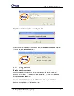
Страница 14: ...checking Launch DS Tool Later 4 1 2 Using DS Tool Explore device servers DS Tool will broadcast to the network and search all available DS devices in the network automatically The default IP address...

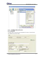
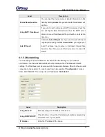
Страница 15: ...r Manual ORing Industrial Networking Corp 14 4 1 3 Configure Device Servers 4 1 3 1 General This page enables you to perform general configuration for the device includes the device name SNTP server a...

Страница 16: ...l IP address Input a value in the Report Interval time based on how often you want the device server to report its status 4 1 3 2 Networking You must assign a valid IP address for the device before at...

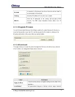
Страница 17: ...nd up to date firmware from ORing s website To update firmware for the device save the firmware file in your host PC and then specify the file location by clicking on the Browsing button and continue...

Страница 18: ...will retrieve saved configuration file and apply it to in current device Export Configuration Saving the current parameters to a file and export it to a current host 4 1 4 Configure Serial Port You ca...

Страница 19: ...m of 9600 bits per second You can select a baud rate from the drop down list which ranges from 110bps to 460800bps Parity Parity is a simple form of error detection which guards data on the cable betw...

Страница 20: ...ware XOFF and OXN is software flow control while RTS CTS or DTR DSR is hardware flow control Choose XOFF to tell the computer to stop sending data then the receiving side will send an XOFF character o...

Страница 21: ...a buffer timeout the data will also be sent You can set the time from 0 to 65535 seconds Force TX Interval Time Force TX interval time is to specify the timeout when no data has been transmitted When...

Страница 22: ...fault value If multilink is configured only the first host connection is effective for this setting Alive Check The serial device will send a TCP alive check package in each defined time interval Aliv...

Страница 23: ...Description Data Port Set the port number for data transmission Auto Scan Scan the data port automatically Idle Timeout When a serial port stops data transmission for a defined period of time Idle Tim...

Страница 24: ...you have settled Startup or any character After the data has been transferred the device can disconnect automatically from the server by using the TCP alive check time or idle time settings Label Des...

Страница 25: ...on Any Character The TCP Client will build a TCP connection once the connected serial device starts to send data UDP Mode Compared to TCP communication UDP is faster and more efficient as you can uni...

Страница 26: ...also enhances access speed and provides a user friendly viewing screen Note By default IE5 0 or later version do not allow Java applets to open sockets You need to modify the browser setting separate...

Страница 27: ...192 168 10 254 User Name admin After logging in you will see the information of the device as below On the left hand side of the management interface shows links to various settings Clicking on the l...

Страница 28: ...s an IP address on connection Choose static if the ISP provides you with a static permanent IP address and does not assign it dynamically You need to set up IP address subnet mask and gateway informat...

Страница 29: ...r the COM port number that modem is connected to Interface Choose an interface for your serial device Available interfaces include RS 232 RS 422 RS 485 2W and RS 485 4W Baud Rate Choose a baud rate in...

Страница 30: ...a bit will always be a logical 0 Flow Control Serial communication consists of hardware flow control and software flow control so called as the control is handled by software or hardware XOFF and OXN...

Страница 31: ...event a TCP port conflict with other applications the user can set the Command port to another port if needed Flush Data Buffer After The received data will be queuing in the buffer until all the deli...

Страница 32: ...nk is configured only the first host connection is effective for this setting Alive Check The serial device will send TCP alive check package in each defined time interval Alive Check to remote host t...

Страница 33: ...fective for this setting Alive Check The serial device will send TCP alive check package in each defined time interval Alive Check to remote host to check the TCP connection If the TCP connection is n...

Страница 34: ...evice will send TCP alive check packages in each defined time interval to remote host to check the TCP connection If the TCP connection is not alive the connection will be closed and the port will be...

Страница 35: ...number of the device Send Port Set the send port number Modbus RTU Slave Mode The Modbus RTU Slave mode allows communications between a host computer and a slave device After a host computer sends a...

Страница 36: ...Destination Host Set the IP address of host and the port number of data port Idle Timeout When serial port stops data transmission for a defined period of time the connection will be closed and the po...

Страница 37: ...onse Wait The serial response timeout in milliseconds Idle Timeout Enter a TCP connection timeout in seconds When no Modbus TCP data is received within this timeout the TCP connection will be dropped...

Страница 38: ...Name This field shows the current login username Old Password Enter the password you currently use to login the system if any New Password Enter a new login password Acceptable characters of this fiel...

Страница 39: ...rt settings for the device Label Description Restart Now Click to restart the device via warm reset 4 2 3 4 Firmware Upgrade ORing launches new firmware constantly to enhance device performance and fu...

Страница 40: ...ore Configurations This page allows you to save configurations or return settings to previous status You can download the configuration file from the Web Note users using old versions of Internet Expl...

Страница 41: ...king Tftp Restore Restore Factory Default Setting Click to reset the device to the factory settings The device will reboot to validate the default settings 4 2 3 6 Miscellaneous This page enables you...

Страница 42: ...ators Power indicator Green On Power is on 10 100 1000Base T X RJ45 port indicator Green for Link Act indicator Dual color LED for speed indicator Green for 1000Mbps Amber for 100Mbps Off for 10Mbps L...

Страница 43: ...RDS 3086 3166G User Manual ORing Industrial Networking Corp 42 EN61000 4 8 EN61000 4 11 Shock IEC60068 2 27 Free Fall IEC60068 2 32 Vibration IEC60068 2 6 Safety EN60950 1 Warranty 5 years...

Отзывы: