background image

Install the LED Board

2.

Set the LED board into the LED assembly.

3.

Install and tighten the two screws.

4.

Position the LED assembly over the flange on the chassis left.

216

Netra Server X5-2 Service Manual • October 2016

Содержание netra X5-2

Страница 1: ...Netra Server X5 2 Service Manual Part No E53601 03 October 2016 ...

Страница 2: ......

Страница 3: ...ous applications including applications that may create a risk of personal injury If you use this software or hardware in dangerous applications then you shall be responsible to take all appropriate fail safe backup redundancy and other measures to ensure its safe use Oracle Corporation and its affiliates disclaim any liability for any damages caused by use of this software or hardware in dangerou...

Страница 4: ...s à risque notamment dans des applications pouvant causer des dommages corporels Si vous utilisez ce logiciel ou matériel dans le cadre d applications dangereuses il est de votre responsabilité de prendre toutes les mesures de secours de sauvegarde de redondance et autres mesures nécessaires à son utilisation dans des conditions optimales de sécurité Oracle Corporation et ses affiliés déclinent to...

Страница 5: ...Available During Server States 23 Access the SP Oracle ILOM 28 Network Management Troubleshooting Guidelines 30 Interpreting Diagnostic LEDs 30 Front Panel LEDs 31 Rear Panel LEDs 33 Troubleshooting Oracle ILOM SP Targets 34 Enable Oracle ILOM Legacy Targets 35 Display Oracle ILOM Log Entries 35 Oracle ILOM Log Entry Filters 36 Display Active Power Consumption 37 Display Information About User Ses...

Страница 6: ...onent Fan Speeds 56 Display Component LED State 57 Oracle ILOM Legacy Targets for LED States 57 Using the Server Fault Remind Button 58 Preparing for Service 61 Safety Information 62 Safety Symbols 62 ESD Measures 62 Antistatic Wrist Strap Use 63 Antistatic Mat 63 Tools Needed for Service 63 Filler Panels 64 Find the Server Serial Number 64 Component Service Task Reference 65 Locate the Server 66 ...

Страница 7: ...cle Solaris 104 Unmount an NVMe Storage Drive Oracle Linux 104 Remove an NVMe Storage Drive 106 Verify Removal of an NVMe Storage Drive Oracle Solaris 107 Verify Removal of an NVMe Storage Drive Oracle Linux 107 Remove the NVMe Switch Card Cables 108 Install the NVMe Switch Card Cables 108 Remove the NVMe Switch Card 110 Install an NVMe Switch Card 110 Install an NVMe Storage Drive 111 Power On an...

Страница 8: ...138 Remove a PCIe Card 139 Install a PCIe Card 141 Verify a PCIe Card 142 Servicing the Battery 145 Remove the Battery 145 Install the Battery 147 Servicing the USB Flash Drive 149 USB Flash Drive LED 149 Remove the USB Flash Drive 150 Install the USB Flash Drive 152 Servicing the System Cables 155 System Cable Configuration 156 Remove the SAS Drive Signal Cable 157 Install the SAS Drive Signal Ca...

Страница 9: ...81 DIMM Configuration 182 DIMM Population Guidelines for Single Processor Servers 183 DIMM Population Guidelines for Dual Processor Servers 184 Locate a Faulty DIMM 185 Remove a DIMM 187 Install a DIMM 190 Verify a DIMM 193 Servicing CPUs 195 CPU Configuration 195 Locate a Faulty CPU 196 CPU Tool 197 Remove a CPU 198 Install a CPU 203 Servicing the LED Board 211 Determine if the LED Board Is Fault...

Страница 10: ...B Is Faulty 237 Remove the PDB 239 Install the PDB 242 Verify the PDB 245 Returning the Server to Operation 247 Install the PSU Duct 248 Install the Air Duct 249 Secure the Drive Cage 253 Install the Fan Tray 255 Install the Top Cover 257 Connect Power Cords 260 Power On the Server Oracle ILOM 261 Power On the Server Power Button 262 Glossary 263 Index 267 10 Netra Server X5 2 Service Manual Octob...

Страница 11: ...ized service providers Required knowledge Advanced experience troubleshooting and replacing hardware Product Documentation Library Documentation and resources for this product and related products are available at http www oracle com goto netra x5 2 docs Feedback Provide feedback about this documentation at http www oracle com goto docfeedback Using This Documentation 11 ...

Страница 12: ...12 Netra Server X5 2 Service Manual October 2016 ...

Страница 13: ... on page 14 Component Locations Motherboard Memory and PCIe Cards on page 16 Front Panel Components Service on page 17 Rear Panel Components Service on page 18 Related Information Detecting and Managing Faults on page 21 Preparing for Service on page 61 Returning the Server to Operation on page 247 Identifying Components 13 ...

Страница 14: ...nent Locations Storage Power and Fan Modules Component Locations Storage Power and Fan Modules No Name Service Links 1 Filter Servicing the Filter on page 89 14 Netra Server X5 2 Service Manual October 2016 ...

Страница 15: ...cable Servicing the System Cables on page 155 9 Drive backplane power cable Servicing the System Cables on page 155 10 Fan modules Servicing Fan Modules on page 129 11 Fan tray Remove the Fan Tray on page 80 Install the Fan Tray on page 255 12 USB board Servicing the USB Board on page 219 13 Power supplies Servicing Power Supplies on page 119 14 DVD drive Servicing the DVD Drive on page 113 Relate...

Страница 16: ...page 253 2 Power supplies Servicing Power Supplies on page 119 3 Fan modules Servicing Fan Modules on page 129 4 PCIe cards Servicing PCIe Cards on page 137 5 USB flash drive Servicing the USB Flash Drive on page 149 6 Air duct Remove the Air Duct on page 83 Install the Air Duct on page 249 7 Battery Servicing the Battery on page 145 8 PSU duct Remove the PSU Duct on page 87 16 Netra Server X5 2 S...

Страница 17: ...s Storage Power and Fan Modules on page 14 Front Panel Components Service on page 17 Rear Panel Components Service on page 18 Component Service Task Reference on page 65 Front Panel Components Service No Description Links 1 Power button Power Off the Server Power Button Graceful on page 69 Power On the Server Power Button on page 262 2 Locator button Front Panel LEDs on page 31 3 Drives bottom row...

Страница 18: ...g the DVD Drive on page 113 4 USB 2 0 ports USB Ports in Netra Server X5 2 Installation Guide 5 RFID module Obtain the Server Serial Number in Netra Server X5 2 Administration Guide Related Information Component Locations Storage Power and Fan Modules on page 14 Component Locations Motherboard Memory and PCIe Cards on page 16 Rear Panel Components Service on page 18 Front Panel LEDs on page 31 Rea...

Страница 19: ...page 28 6 USB 3 0 ports USB Ports in Netra Server X5 2 Installation Guide 7 SER MGT RJ 45 serial port for SP Access the SP Oracle ILOM on page 28 8 Network 100 1000 10000 ports NET0 to NET3 for host 10 Gigabit Ethernet Ports in Netra Server X5 2 Installation Guide 9 Grounding studs Connect the Chassis Ground Wire in Netra Server X5 2 Installation Guide 10 Chassis Status LEDs Locator LED and button...

Страница 20: ...20 Netra Server X5 2 Service Manual October 2016 ...
Страница 21: ...e ILOM Legacy Targets on page 51 Related Information Identifying Components on page 13 Preparing for Service on page 61 Returning the Server to Operation on page 247 Understanding Diagnostics When problems arise during day to day operations of the server you can use these topics to determine the fault of the problem and a course of action Diagnostic Process on page 22 Understanding Diagnostic Tool...

Страница 22: ... 8 8 Fix the supporting hardware Then go to Step 1 9 Check the server 10 Inspect the power supply LEDs See Rear Panel LEDs on page 33 and Power Supply LEDs on page 120 or Oracle ILOM Legacy Targets for LED States on page 57 11 Are any power supply LEDs lit Step 13 Step 12 12 Check the power cords and supplied power See Netra Server X5 2 Installation Guide cabling and specifications Then go to Step...

Страница 23: ...stration 32 Is sufficient information provided to justify a service operation Step 33 Step 34 33 Perform the service operation on the identified component See Resettable Targets on page 51 and Identifying Components on page 13 34 Is the server fully powered up Step 36 Step 35 35 Fully power up the server See Power On the Server Oracle ILOM on page 261 Then go to Step 36 36 Perform general diagnost...

Страница 24: ...ameters for Oracle ILOM See Troubleshooting Oracle ILOM SP Targets on page 34 Oracle ILOM logs These files provide an accounting of events that happened with the server hardware See Display Oracle ILOM Log Entries on page 35 BIOS messages These messages might be displayed The messages describe events occurring during the BIOS power on self test See BIOS POST Event Messages on page 40 Oracle ILOM S...

Страница 25: ...erating system and is installed separately For Oracle VTS software and documentation go to http docs oracle com cd E19719 01 index html Related Information Tools Available When Power Cords Are Attached on page 25 Tools Available on Initial Power Up on page 26 Tools Available When the BIOS Menu Is Available on page 26 Tools Available When the OS Boots on page 27 Tools Available When the OS Is Runni...

Страница 26: ...ted Information Diagnostic Tools on page 24 Tools Available When Power Cords Are Attached on page 25 Tools Available When the BIOS Menu Is Available on page 26 Tools Available When the OS Boots on page 27 Tools Available When the OS Is Running on page 28 Tools Available When the BIOS Menu Is Available In this server state the boot sequence has been suspended and the system is in a quiescent state ...

Страница 27: ...The kernel libraries and drivers are being loaded Tool Links Status LEDs Power supply Chassis Hard drive Network Rear Panel LEDs on page 33 Front Panel LEDs on page 31 Oracle ILOM SP targets Troubleshooting Oracle ILOM SP Targets on page 34 Oracle ILOM logs Display Oracle ILOM Log Entries on page 35 Oracle ILOM System targets Determining Component Health on page 43 Oracle ILOM show faulty command ...

Страница 28: ...and on page 47 Oracle ILOM faultmgt shell Display Faults faultmgmt Shell on page 48 Oracle ILOM legacy targets Troubleshooting Oracle ILOM Legacy Targets on page 51 Diagnostic applications Refer to your application documentation Related Information Diagnostic Tools on page 24 Tools Available When Power Cords Are Attached on page 25 Tools Available on Initial Power Up on page 26 Tools Available Whe...

Страница 29: ...s of interaction with the SP are through the Oracle ILOM CLI For more information about the Oracle ILOM web interface see Server Administration accessing the Oracle ILOM web interface 3 Open an SSH session and connect to the SP by specifying its IP address The Oracle ILOM default username is root and the default password is changeme ssh root xxx xxx xxx xxx Are you sure you want to continue connec...

Страница 30: ... SSH set SP services ssh state enabled HTTP set SP services http secureredirect disabled servicestate enabled HTTPS set SP services https servicestate enabled Use an industry standard network diagnostic tool like IPv4 Ping or Traceroute to test the network connections between the server and the management device Related Information Diagnostic Process on page 22 Understanding Diagnostic Tools Avail...

Страница 31: ...ondition 2 Rear Power Supply Status LED amber Indicates the state of the power supplies Off Indicates a steady state no service action is required On Indicates a fault with one of the power supplies 3 SP Status LED Indicates the state of the SP Green flashing Indicates the SP is booting Green steady Indicates the SP booted and OK no service action is required 4 OK LED green Indicates these conditi...

Страница 32: ... addition to the Service Action Required LED 6 Locator LED and button white The Locator LED can be turned on to identify a particular system When on the LED blinks rapidly Pressing and holding the Locator button for 5 seconds initiates a test of all LEDs in the LED assembly 7 Hard Drive Status LEDs Ready to Remove LED top blue Indicates that the drive can be removed during a hot plug operation Ser...

Страница 33: ...atus LEDs Locator LED and button left white The Locator LED can be turned on to identify a particular system When on the LED blinks rapidly There are two methods for turning a Locator LED on Typing the Oracle ILOM command set SYS LOCATE value Fast_Blink Pressing the Locator button Service Action Required LED center amber Indicates that service is required POST and Oracle ILOM are two diagnostics t...

Страница 34: ... operating as a 100 Mbps connection 4 NET0 to NET3 Status LEDs Link and Activity LED left green Indicates these conditions On A link is established Blinking Indicates activity on the link Off No link is established Speed LED right amber green Indicates these conditions Green The link is operating as a 10000 Mbps connection Amber The link is operating as a Gigabit connection 1000 Mbps Off The link ...

Страница 35: ...edure 1 Access Oracle ILOM See Access the SP Oracle ILOM on page 28 2 Enable the Oracle ILOM legacy targets set SP cli legacy_targets enabled Set legacy_targets to enabled 3 You can now perform diagnostics with Oracle ILOM legacy targets See Troubleshooting Oracle ILOM Legacy Targets on page 51 Related Information Display Oracle ILOM Log Entries on page 35 Oracle ILOM Log Entry Filters on page 36 ...

Страница 36: ...is provided for more information about the fault Related Information Enable Oracle ILOM Legacy Targets on page 35 Oracle ILOM Log Entry Filters on page 36 Display Active Power Consumption on page 37 Display Information About User Sessions on page 38 Display the NET MGT Configuration Properties on page 39 Display the SP Firmware Version on page 40 Oracle ILOM Log Entry Filters When you display the ...

Страница 37: ...he Severity parameter The Severity parameter has one of five values Debug Down Critical Major Minor For example to display only log entries indicating a minor change to the system inventory type show SP logs event list Class Chassis Type State Severity Minor Note The Critical Major and Minor values for the Severity parameter do not necessarily corollate to the Critical Major and Minor alarm states...

Страница 38: ...essions on page 38 Display the NET MGT Configuration Properties on page 39 Display the SP Firmware Version on page 40 Display Information About User Sessions 1 Access Oracle ILOM See Access the SP Oracle ILOM on page 28 2 Display the user session numbers show d targets SP sessions SP sessions Targets 4 current In this example there is only one user session number 4 3 Display information about a pa...

Страница 39: ...OM See Access the SP Oracle ILOM on page 28 2 Display the parameters configured for the SP to communicate over the network show d properties SP network SP network Properties commitpending Cannot show property dhcp_clientid none dhcp_server_ip none ipaddress 10 153 113 85 ipdiscovery static ipgateway 10 153 113 1 ipnetmask 255 255 255 0 state enabled Related Information Enable Oracle ILOM Legacy Ta...

Страница 40: ...isplay the NET MGT Configuration Properties on page 39 BIOS POST Event Messages During BIOS power on self test these event messages might be displayed BIOS POST Event Message Cause ACPI Power state User has configured a soft power off Boot media failure No bootable media was found BIOS was configured to boot off of removable media yet none is available Alternatively bootable media is available but...

Страница 41: ...ther disabled or defective The boot process terminates Option ROM initialization Option ROMs are being initialized Option ROM space exhausted Memory space allocated for BIOS options is full and writes to the space cannot continue The remaining options are not configured Primary processor initialization Primary CPU is being initialized PXE server not found BIOS was configured to boot from a PXE ser...

Страница 42: ...ated Information Understanding Diagnostics on page 21 Interpreting Diagnostic LEDs on page 30 Troubleshooting Oracle ILOM SP Targets on page 34 BIOS POST Event Messages on page 40 Displaying Faulty Components on page 46 Troubleshooting Oracle ILOM Legacy Targets on page 51 Display Problematic Components 1 Access Oracle ILOM See Access the SP Oracle ILOM on page 28 2 Display a table of problematic ...

Страница 43: ...ning Component Health on page 43 Determining Component Health When a component or system of components experiences a fault it becomes unhealthy These topics enable you to display component health states Display the General Health of Component Systems on page 43 Display Health and Information About Specific Components on page 44 Component Health Targets on page 45 Oracle ILOM Target Health States o...

Страница 44: ...le ILOM Target Health States on page 45 Display Health and Information About Specific Components 1 Access Oracle ILOM See Access the SP Oracle ILOM on page 28 2 Type show target where these components have these targets Component Target Comment CPUs System Processors CPUs CPU_x where x is either 0 or 1 DIMMs System Memory DIMMs DIMM_x where x is the number of the DIMM 0 to 15 Fan modules SYS MB Fa...

Страница 45: ... System Memory DIMMs DIMM_x Individual DIMMs where x is 0 to 15 System Power Power system System Power Power_Supplies Power_Supply_x Individual power supplies where x is either 0 or 1 System Cooling Cooling system System Cooling Fans Fan_x Individual fans where x is 0 to 9 System Networking Networking system System Networking Ethernet_NICs Ethernet_NIC_x Individual network interfaces where x is 0 ...

Страница 46: ...ffline health status appears when the action property is set to Prepare to Remove and the hardware component has not been removed from the chassis Related Information Display the General Health of Component Systems on page 43 Display Health and Information About Specific Components on page 44 Component Health Targets on page 45 Displaying Faulty Components If Oracle ILOM has automatically determin...

Страница 47: ...message ID and so on This is an example of a faulty power supply Note The characters SPT at the beginning of the message ID indicate that the fault was detected by Oracle ILOM Note The component property provides the Oracle ILOM target of the component that faulted and might need to be replaced You can use the information in the table of Resettable Targets on page 51 to further identify the compon...

Страница 48: ...ILOM faultmgmt shell For more information about the Oracle Solaris fault manager commands refer to Server Administration and the Oracle Solaris documentation 1 Access Oracle ILOM See Access the SP Oracle ILOM on page 28 2 Access the faultmgmt shell start SP faultmgmt shell Are you sure you want to start SP faultmgmt shell y n y 3 At the faultmgmtsp prompt display any current faults faultmgmtsp fma...

Страница 49: ...there are insufficient power supplies operational Action The administrator should review the ILOM event log for additional information pertaining to this diagnosis Please refer to the Details section of the Knowledge Article for additional information 4 Optional Display the fault history faultmgmtsp fmdump TIMESTAMP UUID MSGID 2011 12 20 06 00 14 52db4790 1d30 e1d5 b4e3 8bf677246bd2 ILOM 8000 30 2...

Страница 50: ...e ILOM automatically clears the fault However if the host detects a fault you must manually clear the fault from Oracle ILOM after resolution by resetting the component 1 Access Oracle ILOM See Access the SP Oracle ILOM on page 28 2 Reset the component to clear the fault manually set target clear_fault_action true where target is the Oracle ILOM target of the faulted component See Resettable Targe...

Страница 51: ... either 0 or 1 SYS MB Px Dy DIMM y of CPU x where y is 0 to 11 and x is either 0 or 1 SYS MB FMx Fan module x where x is 0 to 4 SYS SP SP SYS PSx Power supply x where x is either 0 or 1 SYS PDB PDB SYS DBP Drive backplane Related Information Display Faults show faulty Command on page 47 Display Faults faultmgmt Shell on page 48 Clear a Fault Manually on page 50 Troubleshooting Oracle ILOM Legacy T...

Страница 52: ... SP Targets on page 34 BIOS POST Event Messages on page 40 Troubleshooting Oracle ILOM System Targets on page 42 Displaying Faulty Components on page 46 Display FRUID and Fault State for Specific Components 1 Access Oracle ILOM See Access the SP Oracle ILOM on page 28 2 If you have not already done so enable Oracle ILOM legacy targets See Enable Oracle ILOM Legacy Targets on page 35 3 Type show ta...

Страница 53: ... Px Drive backplane SYS DBP where x is 0 to 5 Fan module FMx SYS MB FMx Motherboard SYS MB NETx port SYS MB NETx where x is 0 to 3 NVRAM or IDPROM SYS MB CPLD PDB SYS PDB Power supply PSx SYS PSx where x is either 0 or 1 SP SYS SP Related Information Display FRUID and Fault State for Specific Components on page 52 Oracle ILOM Legacy Targets for Component Power Consumption on page 55 Oracle ILOM Le...

Страница 54: ...y Component Fan Speeds on page 56 Display Component LED State on page 57 Display Component Power Consumption Note For the chassis CPUs DIMMs and fans a summary of power consumed is displayed 1 Access Oracle ILOM See Access the SP Oracle ILOM on page 28 2 If you have not already done so enable Oracle ILOM legacy targets See Enable Oracle ILOM Legacy Targets on page 35 3 Type show target where targe...

Страница 55: ...S VPS_CPUS history 1 list 14 day history DIMM power summary SYS VPS_MEMORY history DIMM power timeline SYS VPS_MEMORY history 1 list 14 day history Fan power summary SYS VPS_FANS history Fan power timeline SYS VPS_FANS history 1 list 14 day history Power supply PSx drawn SYS PSx P_IN value where x is either 0 or 1 Power supply PSx supplied SYS PSx P_OUT value where x is either 0 or 1 Related Infor...

Страница 56: ... State for Specific Components on page 52 Display Component Voltages on page 53 Display Component Power Consumption on page 54 Display Component Fan Speeds on page 56 Display Component LED State on page 57 Display Component Fan Speeds 1 Access Oracle ILOM See Access the SP Oracle ILOM on page 28 2 If you have not already done so enable Oracle ILOM legacy targets See Enable Oracle ILOM Legacy Targe...

Страница 57: ...Enable Oracle ILOM Legacy Targets on page 35 3 Type show target value where target is from the table in Oracle ILOM Legacy Targets for LED States on page 57 Related Information Display FRUID and Fault State for Specific Components on page 52 Display Component Voltages on page 53 Display Component Power Consumption on page 54 Display Component Temperatures on page 55 Display Component Fan Speeds on...

Страница 58: ...omponent FRUID and Fault States on page 53 Oracle ILOM Legacy Targets for Component Power Consumption on page 55 Display Component LED State on page 57 Using the Server Fault Remind Button When the server Fault Remind button is pressed an LED located next to the Fault Remind button lights green to indicate that there is sufficient voltage present in the fault remind circuit to light any fault LEDs...

Страница 59: ...Using the Server Fault Remind Button Detecting and Managing Faults 59 ...

Страница 60: ...60 Netra Server X5 2 Service Manual October 2016 ...
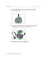
Страница 61: ...page 67 8 Move the server out of the rack and open the top cover Accessing Internal Components on page 71 You can now service the fan modules the PCIe cards the battery and the USB flash drive Servicing Fan Modules on page 129 Servicing PCIe Cards on page 137 Servicing the Battery on page 145 Servicing the USB Flash Drive on page 149 9 Remove the fan tray Remove the Fan Tray on page 80 You can now...

Страница 62: ...tage and frequency of your power source match the voltage and frequency inscribed on the equipment s electrical rating label Follow the electrostatic discharge safety practices as described here Safety Symbols Note the meanings of these symbols that might appear in this document Caution There is a risk of personal injury or equipment damage To avoid personal injury and equipment damage follow the ...

Страница 63: ...ds or express modules When servicing or removing server components attach an antistatic strap to your wrist and then to a metal area on the chassis Following this practice equalizes the electrical potentials between you and the server Antistatic Mat Place ESD sensitive components such as motherboards memory and other PCBs on an antistatic mat These items can be used as an antistatic mat Antistatic...

Страница 64: ...stem If you remove a filler panel and continue to operate your server with an empty slot the server might overheat due to improper airflow For instructions on removing or installing a filler panel for a server component refer to the topic in this document about servicing that component Related Information Component Service Task Reference on page 65 Servicing SAS Drives on page 93 Servicing PCIe Ca...

Страница 65: ... MB Px Dy Servicing DIMMs on page 181 Drives SYS DBP HDDx Servicing SAS Drives on page 93 Drive backplanes SYS DBP Servicing the Drive Backplane on page 171 DVD drive Servicing the DVD Drive on page 113 Fan modules SYS MB FMx Servicing Fan Modules on page 129 Filter Servicing the Filter on page 89 LED board Servicing the LED Board on page 211 Motherboard SYS MB Servicing the Motherboard on page 22...

Страница 66: ...or LED set SYS LOCATE value Fast_Blink The white Locator LEDs one on the front panel and one on the rear panel blink 4 After locating the server with the blinking Locator LED turn the LED off by pressing the Locator button Note Alternatively you can turn off the Locator LED by running the Oracle ILOM set SYS LOCATE value off command 5 Consider your next step Service these components Servicing the ...

Страница 67: ... and Data Cables on page 70 Related Information Accessing Internal Components on page 71 Returning the Server to Operation on page 247 Prepare to Power Off the Server Perform this procedure before powering off the server 1 Notify affected users that the server will be shut down Refer to the Oracle Solaris system administration documentation for additional information 2 Save any open files and quit...

Страница 68: ... Additional information about powering off the server is provided in Server Administration 1 Access Oracle ILOM See Access the SP Oracle ILOM on page 28 Depending on the type of problem you might want to view server status or log files You also might want to run diagnostics before you shut down the server See Detecting and Managing Faults on page 21 2 Power off the server stop System Are you sure ...

Страница 69: ...n page 67 Disconnect Power Cords and Data Cables on page 70 Power On the Server Power Button on page 262 Front Panel Components Service on page 17 Power Off the Server Oracle ILOM on page 68 Power Off the Server Emergency Shutdown on page 69 Power Off the Server Emergency Shutdown Caution For this procedure all applications and files are closed abruptly without saving changes File system corruptio...

Страница 70: ...he Server Oracle ILOM on page 68 Power Off the Server Power Button Graceful on page 69 Power Off the Server Emergency Shutdown on page 69 2 Unplug all power cords from the server Caution Because 3 3 VDC standby power is always present in the system you must unplug the power cords before accessing any cold serviceable components For AC power cords For DC power cords 70 Netra Server X5 2 Service Man...

Страница 71: ...ergency Shutdown on page 69 Prevent ESD Damage on page 72 Connect Power Cords on page 260 Accessing Internal Components These topics provide procedures and guidelines when accessing internal components Step Description Link 1 Take antistatic precautions now Prevent ESD Damage on page 72 2 Move the server out of the rack Removing the Server From the Rack on page 72 3 Gain access to the internal com...

Страница 72: ...antistatic mat 2 Attach an antistatic wrist strap When servicing or removing server components attach an antistatic strap to your wrist and then to a metal area on the chassis Related Information Disconnect Power Cords and Data Cables on page 70 Removing the Server From the Rack on page 72 Remove the Top Cover on page 77 Safety Information on page 62 Removing the Server From the Rack Before you ca...

Страница 73: ... the server from a 4 post 19 inch rack depend on the type of rack or rail kit The server is hard mounted with the hardmount rack kit or the server is mounted with a sliding rail kit 1 Support the weight of the server for removal 2 For the hardmount rack kit remove the two screws securing each rear mount support bracket Preparing for Service 73 ...

Страница 74: ...e rails to pull the server out of the rack 5 Lift the server from the rack and set it aside on an antistatic mat 6 Remove the top cover See Remove the Top Cover on page 77 Related Information Prevent ESD Damage on page 72 Remove the Top Cover on page 77 Install the Top Cover on page 257 Safety Information on page 62 Remove the Server From the 2 Post 19 inch Rack 1 Support the weight of the server ...

Страница 75: ...Remove the Server From the 2 Post 19 inch Rack 2 Remove the two screws that secure each rear plate to the back of the post Preparing for Service 75 ...

Страница 76: ...m the 2 Post 19 inch Rack 3 Loosen the two screws that secure each rear plate to the eyelets of the side bracket 4 Slide each rear plate out of the eyelets and set them aside 76 Netra Server X5 2 Service Manual October 2016 ...

Страница 77: ... antistatic mat 7 Remove the top cover See Remove the Top Cover on page 77 Related Information Prevent ESD Damage on page 72 Remove the Top Cover on page 77 Install the Top Cover on page 257 Safety Information on page 62 Remove the Top Cover 1 Remove the server from the rack See Removing the Server From the Rack on page 72 Preparing for Service 77 ...

Страница 78: ...Remove the Top Cover 2 Fully loosen the two captive screws at the rear of the top cover 78 Netra Server X5 2 Service Manual October 2016 ...
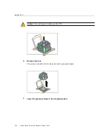
Страница 79: ...up and off the chassis Set the top cover aside 4 Consider your next step Service these components Servicing Fan Modules on page 129 Servicing PCIe Cards on page 137 Servicing the Battery on page 145 Servicing the USB Flash Drive on page 149 Or remove the fan tray Preparing for Service 79 ...

Страница 80: ...ver From the Rack on page 72 Install the Top Cover on page 257 Safety Information on page 62 Remove the Fan Tray 1 Complete these prerequisites in this order Remove the Top Cover on page 77 Remove a Fan Module on page 132 Remove all fan modules 2 Open the two fan tray locks 80 Netra Server X5 2 Service Manual October 2016 ...

Страница 81: ... hard drive power or DVD SATA cables See Servicing the System Cables on page 155 Or pivot the drive cage See Rotate the Drive Cage to the Service Position on page 82 Related Information Remove the Top Cover on page 77 Install the Fan Tray on page 255 Rotate the Drive Cage to the Service Position on page 82 Preparing for Service 81 ...

Страница 82: ...on page 80 2 Disconnect the cables attached to the drive backplane and the cable attached to the USB board The cables are shown in the illustration in System Cable Configuration on page 156 Note Depending on your server s configuration you might not have the DVD SATA cable or the NVMe drive cables as seen in the illustration 3 Fully loosen the four screws securing the drive cage to the chassis 82 ...

Страница 83: ...page 171 Or remove the air duct See Remove the Air Duct on page 83 Related Information Remove the Fan Tray on page 80 Secure the Drive Cage on page 253 Remove the Air Duct on page 83 Remove the Air Duct 1 Complete these prerequisites in this order Remove the Top Cover on page 77 Rotate the Drive Cage to the Service Position on page 82 Preparing for Service 83 ...

Страница 84: ...Remove the Air Duct 2 Disconnect the cables and move them out of the way 3 Fully loosen the thumbscrew on the left bracket 84 Netra Server X5 2 Service Manual October 2016 ...

Страница 85: ...Remove the Air Duct 4 Slide the left L thumbscrew bracket forward and off of the mounting pins 5 Set the thumbscrew bracket aside Preparing for Service 85 ...

Страница 86: ...rvice these components Servicing DIMMs on page 181 Servicing the LED Board on page 211 Or remove the PSU duct See Remove the PSU Duct on page 87 Related Information Rotate the Drive Cage to the Service Position on page 82 Install the Air Duct on page 249 Remove the PSU Duct on page 87 86 Netra Server X5 2 Service Manual October 2016 ...

Страница 87: ...rvice Position on page 82 2 Lift the PSU duct up and out of the chassis 3 Set the PSU duct aside 4 Consider your next step Continue servicing the USB board See Servicing the USB Board on page 219 Service the DIMMs See Servicing DIMMs on page 181 Service the PDB See Servicing the PDB on page 237 Service the PDB signal cable Preparing for Service 87 ...

Страница 88: ...Remove the PSU Duct See Servicing the System Cables on page 155 Related Information Remove the Air Duct on page 83 Install the PSU Duct on page 248 88 Netra Server X5 2 Service Manual October 2016 ...

Страница 89: ...omponent s service operation Install the Filter on page 91 Related Information Identifying Components on page 13 Detecting and Managing Faults on page 21 Component Service Task Reference on page 65 Preparing for Service on page 61 Returning the Server to Operation on page 247 Remove the Filter Removing the filter is a hot swap operation You do not need to power off the server before you remove the...

Страница 90: ...ide 6 Consider your next step If you removed the filter as part of a replacement operation install a new filter See Install the Filter on page 91 If you removed the filter as part of another component s removal or installation procedure return to that procedure See Component Service Task Reference on page 65 for assistance 90 Netra Server X5 2 Service Manual October 2016 ...

Страница 91: ...g the filter 1 Consider your first step If you are replacing the filter remove the faulty or obsolete filter first then return to this procedure Step 2 See Remove the Filter on page 89 If you are installing the filter as part of another component s removal or installation procedure go to Step 2 2 Set the bottom edge of the filter into the lip at the front of the chassis The left and right release ...

Страница 92: ...as part of another component s removal or installation procedure return to that procedure See Component Service Task Reference on page 65 for assistance Related Information Remove the Filter on page 89 Preparing for Service on page 61 Returning the Server to Operation on page 247 92 Netra Server X5 2 Service Manual October 2016 ...
Страница 93: ...rvice operation Remove a SAS Drive on page 97 Install a drive as part of another component s service operation Install a SAS Drive on page 99 Add additional drives SAS Drive Configuration on page 94 Install a SAS Drive on page 99 Verify a SAS Drive on page 101 Decrease the number of existing drives Remove a SAS Drive on page 97 Identify a faulty drive SAS Drive LEDs on page 94 Locate a Faulty Driv...

Страница 94: ...VD drive Nor is it possible to swap a DVD drive for drives 6 and 7 The drive cages are specific for the configurations and are not interchangeable Caution Overheating hazard There must be no empty drive slots The filters for the two configurations are also configuration specific Related Information Install a SAS Drive on page 99 SAS Drive LEDs on page 94 Locate a Faulty Drive on page 95 SAS Drive ...

Страница 95: ...ty Drive on page 95 SAS Drive Configuration on page 94 Remove a SAS Drive on page 97 Front Panel LEDs on page 31 Rear Panel LEDs on page 33 Locate a Faulty Drive You must determine which drive is faulty before you replace it 1 Check to see if any System Service Required LEDs are lit or flashing See Interpreting Diagnostic LEDs on page 30 2 Visually inspect the installed drives to see if any of the...

Страница 96: ...ou will see SYS DBP HDDx under the Value heading where x is 0 to 7 For example show faulty Target Property Value SP faultmgmt 0 fru SYS DBP HDD0 If a drive is faulty replace it See Remove a SAS Drive on page 97 If a FRU value different from SYS DBP HDDx is displayed see Component Service Task Reference on page 65 to identify which component is faulty 6 Use the Oracle ILOM faultmgmt shell to identi...

Страница 97: ...now See Preparing for Service on page 61 If you are removing a drive as part of another component s removal or installation procedure go to Step 3 3 Remove the filter See Remove the Filter on page 89 4 Determine if you need to shut down the OS to remove the drive and perform one of these actions If the drive cannot be taken offline without shutting down the OS follow instructions in Power Off the ...

Страница 98: ...next step If you removed a drive as part of a replacement operation install a new drive See Install a SAS Drive on page 99 If you removed a drive as part of another component s removal or installation procedure return to that procedure See Component Service Task Reference on page 65 for assistance If you are not replacing the drive install a drive filler panel in its place See Install a SAS Drive ...

Страница 99: ... a drive filler panel 1 Consider your first step If you are replacing a drive remove the faulty or obsolete drive first then return to this procedure Step 3 See Remove a SAS Drive on page 97 If you are installing a new or an additional drive go to Step 2 If you are installing a drive as part of another component s removal or installation procedure go to Step 3 2 Review this information and complet...

Страница 100: ...e the drive into the chassis until the release lever moves slightly inward 6 Press the release lever fully closed with a click securing the drive into the chassis 7 Repeat from Step 3 through Step 6 for any additional drives that you are installing 8 Consider your next step If you installed a drive as part of a replacement operation go to Step 9 100 Netra Server X5 2 Service Manual October 2016 ...

Страница 101: ... page 247 Verify a SAS Drive on page 101 Related Information Remove a SAS Drive on page 97 Verify a SAS Drive on page 101 SAS Drive Configuration on page 94 Preparing for Service on page 61 Returning the Server to Operation on page 247 Verify a SAS Drive After you install a SAS drive you can verify its functionality 1 Access Oracle ILOM See Access the SP Oracle ILOM on page 28 2 Check for the pres...

Страница 102: ...aced drive you might need to perform administrative tasks to reinstall software before the server can boot Refer to the OS documentation for more information 5 Verify that the blue Ready to Remove LED is no longer lit on the drive that you installed See SAS Drive LEDs on page 94 6 If the previous steps indicate that the drive is functioning properly perform the tasks required to configure the driv...

Страница 103: ...nmount an NVMe Storage Drive Oracle Solaris on page 104 Unmount an NVMe Storage Drive Oracle Linux on page 104 Remove an NVMe Storage Drive on page 106 Verify Removal of an NVMe Storage Drive Oracle Solaris on page 107 Verify Removal of an NVMe Storage Drive Oracle Linux on page 107 Remove the NVMe Switch Card Cables on page 108 Install the NVMe Switch Card Cables on page 108 Remove the NVMe Switc...

Страница 104: ...mounted The state of the slot must be PRESENT hotplug list lc Connection State Description Path pcie13 PRESENT PCIe Native pci 7a 0 pci8086 2f08 3 pci111d 80b5 4 Related Information Remove an NVMe Storage Drive on page 106 Verify Removal of an NVMe Storage Drive Oracle Solaris on page 107 Unmount an NVMe Storage Drive Oracle Linux 1 Log in to Oracle Linux 2 Remove the NVMe storage device path a Fi...

Страница 105: ...ot correspond to the NVMe drive labels on the server For example pci slots 12 address 0000 b2 00 corresponds to instance nvme0 However on the server this drive is labeled NVMe2 c Disconnect all users of the NVMe drive and back up the NVMe drive data as needed i Use the umount command to unmount any file systems that are mounted on the device ii Remove the device from any multiple device md and Log...

Страница 106: ...ge 97 1 Unmount the storage drive depending on the OS Use one of these methods Unmount an NVMe Storage Drive Oracle Solaris on page 104 Unmount an NVMe Storage Drive Oracle Linux on page 104 2 Identify the physical location of the NVMe drive that you want to remove For storage drive locations see Component Locations Storage Power and Fan Modules on page 14 3 Verify that the OK to Remove indicator ...

Страница 107: ...on of an NVMe Storage Drive on page 112 Verify Removal of an NVMe Storage Drive Oracle Solaris This task uses pcie13 as an example At the superuser prompt type The state of the slot must be EMPTY hotplug list lc Connection State Description Path pcie13 EMPTY PCIe Native pci 7a 0 pci8086 2f08 3 pci111d 80b5 4 Related Information Unmount an NVMe Storage Drive Oracle Solaris on page 104 Remove an NVM...

Страница 108: ...before servicing the cables 1 Prepare the server for service See Preparing for Service on page 61 2 Disconnect the NVMe cables from the Oracle PCIe NVMe switch card Press each latch and then pull out to disengage the cable from each connector 3 Disconnect the NVMe cables from the front storage drive backplane Press each latch and then pull out to disengage the cable from each connector 4 Remove th...

Страница 109: ...le to ensure proper NVMe cable connections Note Each NVMe cable contains a matching label that corresponds to the port on the Oracle PCIe NVMe switch card For example the NVMe cable labeled 0 1 plugs in to the Oracle PCIe NVMe switch card port 0 1 and the cable labeled 2 3 plugs in to the Oracle PCIe NVMe switch card port 2 3 Disk Backplane Cable Connector Oracle PCIe NVMe Switch Card Port Cable C...

Страница 110: ...e switch card The steps to physically install the switch card are the same as the steps for PCIe cards For detailed instructions see Install a PCIe Card on page 141 Related Information Remove the NVMe Switch Card Cables on page 108 Install the NVMe Switch Card Cables on page 108 Install an NVMe Switch Card on page 110 Install an NVMe Switch Card 1 Prepare the server for service See Preparing for S...

Страница 111: ...which it is installed You must install a replacement drive in the same slot as the drive that was removed 4 Slide the drive into the slot until the drive is fully seated 5 Close the drive latch to lock the drive in place Related Information Power On an NVMe Storage Drive and Attach a Device Driver Oracle Solaris on page 111 Power On an NVMe Storage Drive and Attach a Device Driver Oracle Linux on ...

Страница 112: ... storage drive Related Information Install an NVMe Storage Drive on page 111 Verify the Operation of an NVMe Storage Drive on page 112 Verify the Operation of an NVMe Storage Drive Perform one of the following steps Check the var log messages log file Type the ls l dev nvme command Related Information Verify Removal of an NVMe Storage Drive Oracle Solaris on page 107 Verify Removal of an NVMe Stor...

Страница 113: ...ve as part of another component s service operation Install the DVD Drive on page 116 Related Information Identifying Components on page 13 Detecting and Managing Faults on page 21 Component Service Task Reference on page 65 Preparing for Service on page 61 Returning the Server to Operation on page 247 Remove the DVD Drive Removing the DVD drive is a hot plug operation You do not need to power off...

Страница 114: ...mponent s removal or installation procedure go to Step 3 2 Remove any media from DVD drive 3 Remove the filter See Remove the Filter on page 89 4 Remove the far right drive located beneath the DVD drive See Remove a SAS Drive on page 97 5 Grasp the tab under the right side of the DVD drive and pull the tab out 114 Netra Server X5 2 Service Manual October 2016 ...

Страница 115: ...tion install a new DVD drive See Install the DVD Drive on page 116 If you removed the DVD drive as part of another component s removal or installation procedure return to that procedure See Component Service Task Reference on page 65 for assistance Related Information Install the DVD Drive on page 116 Preparing for Service on page 61 Returning the Server to Operation on page 247 Servicing the DVD ...

Страница 116: ...irst then return to this procedure Step 2 See Remove the DVD Drive on page 113 If you are installing the DVD drive as part of another component s removal or installation procedure go to Step 2 2 Extend the tab out from the underside of the DVD drive 3 Align the DVD drive to the location where it installs into the chassis The DVD drive is oriented with the tab at the right front 4 Slide the DVD dri...

Страница 117: ...ment operation go to Step 8 If you installed the DVD drive as part of another component s removal or installation procedure return to that procedure See Component Service Task Reference on page 65 for assistance 8 Install the drive that you removed previously See Install a SAS Drive on page 99 9 Install the filter See Install the Filter on page 91 10 Finish the installation procedure Servicing the...

Страница 118: ...Returning the Server to Operation on page 247 Related Information Remove the DVD Drive on page 113 Preparing for Service on page 61 Returning the Server to Operation on page 247 118 Netra Server X5 2 Service Manual October 2016 ...
Страница 119: ...nother component s service operation Remove a Power Supply on page 122 Install a power supply as part of another component s service operation Install a Power Supply on page 125 Add additional power supplies Install a Power Supply on page 125 Verify a Power Supply on page 126 Decrease the number of existing power supplies Remove a Power Supply on page 122 Identify a faulty power supply Power Suppl...

Страница 120: ...ff Input power not present Related Information Locate a Faulty Power Supply on page 120 Remove a Power Supply on page 122 Front Panel LEDs on page 31 Rear Panel LEDs on page 33 Locate a Faulty Power Supply You must determine which power supply is faulty before you replace it 1 Check to see if any System Service Required LEDs are lit or flashing See Interpreting Diagnostic LEDs on page 30 2 Visuall...

Страница 121: ...upply is faulty If a power supply is faulty you will see SYS PSx under the Value heading where x is 0 lower power supply or 1 upper power supply For example show faulty Target Property Value SP faultmgmt 0 fru SYS PS0 If a power supply is faulty replace it See Remove a Power Supply on page 122 If a FRU value different from SYS PSx is displayed see Component Service Task Reference on page 65 to ide...

Страница 122: ...y on page 126 Detecting and Managing Faults on page 21 Remove a Power Supply Removing a power supply is a hot swap operation You do not need to power off the server before you remove the power supply 1 Determine which power supply to remove See Locate a Faulty Power Supply on page 120 2 Consider your next step If you have not prepared for service do so now See Preparing for Service on page 61 If y...

Страница 123: ...Remove a Power Supply 4 Press the release tab to the left and pull on the handle Servicing Power Supplies 123 ...

Страница 124: ... See Install a Power Supply on page 125 If you removed a power supply as part of another component s removal or installation procedure return to that procedure See Component Service Task Reference on page 65 for assistance Related Information Locate a Faulty Power Supply on page 120 Install a Power Supply on page 125 Preparing for Service on page 61 Returning the Server to Operation on page 247 12...

Страница 125: ...n return to this procedure Step 2 See Remove a Power Supply on page 122 If you are installing a power supply as part of another component s removal or installation procedure go to Step 2 2 Align the power supply to the location where it installs into the chassis The PDB connector is toward the chassis and the release tab is on the left 3 Slide the power supply into the chassis until the power supp...

Страница 126: ...page 126 Related Information Remove a Power Supply on page 122 Verify a Power Supply on page 126 Preparing for Service on page 61 Returning the Server to Operation on page 247 Verify a Power Supply After you install a power supply you can verify its functionality 1 Access Oracle ILOM See Access the SP Oracle ILOM on page 28 2 Reset the power supply set SYS PSx clear_fault_action true Are you sure ...

Страница 127: ...roperties value 12 027 Volts where x is 0 lower power supply or 1 upper power supply Related Information Install a Power Supply on page 125 Power Supply LEDs on page 120 Locate a Faulty Power Supply on page 120 Servicing Power Supplies 127 ...

Страница 128: ...128 Netra Server X5 2 Service Manual October 2016 ...

Страница 129: ... fan module as part of another component s service operation Remove a Fan Module on page 132 Install a fan module as part of another component s service operation Install a Fan Module on page 133 Add additional fan modules Install a Fan Module on page 133 Verify a Fan Module on page 136 Decrease the number of existing fan modules Remove a Fan Module on page 132 Identify a faulty fan module Fan Mod...

Страница 130: ...n modules Pressing the Fault Remind button on the motherboard illumates the fan module LED for a faulty fan module See Using the Server Fault Remind Button on page 58 No Description 1 Fault Remind button 2 Fan Fault LEDs Related Information Locate a Faulty Fan Module on page 131 Remove a Fan Module on page 132 130 Netra Server X5 2 Service Manual October 2016 ...

Страница 131: ... faulty you will see SYS MB FMx under the Value heading where x is 0 to 4 For example show faulty Target Property Value SP faultmgmt 0 fru SYS MB FM0 If a fan module is faulty replace it See Remove a Fan Module on page 132 If a FRU value different from SYS MB FMx is displayed see Component Service Task Reference on page 65 to identify which component is faulty 4 Use the Oracle ILOM faultmgmt shell...

Страница 132: ...a Fan Module on page 132 Fan Module LEDs on page 130 Verify a Fan Module on page 136 Detecting and Managing Faults on page 21 Remove a Fan Module Removing a fan module is a cold service operation You must power off the server before you remove the fan module 1 Determine which fan module to remove See Locate a Faulty Fan Module on page 131 2 Consider your next step If you have not prepared for serv...

Страница 133: ...nstall a Fan Module on page 133 If you removed a fan module as part of another component s removal or installation procedure return to that procedure See Component Service Task Reference on page 65 for assistance Related Information Locate a Faulty Fan Module on page 131 Install a Fan Module on page 133 Preparing for Service on page 61 Returning the Server to Operation on page 247 Install a Fan Mo...

Страница 134: ...le on page 132 If you are installing a fan module as part of another component s removal or installation procedure go to Step 2 2 Align the fan module to the location where it installs into the fan tray The green band is on the top of the fan module and the arrow points to the rear of the chassis 3 Lower the fan module into the fan tray 134 Netra Server X5 2 Service Manual October 2016 ...

Страница 135: ...module as part of another component s removal or installation procedure return to that procedure See Component Service Task Reference on page 65 for assistance 7 Complete these postrequisites in this order to finish the installation procedure Returning the Server to Operation on page 247 Verify a Fan Module on page 136 Related Information Remove a Fan Module on page 132 Verify a Fan Module on page...

Страница 136: ...le to 4 right fan module 3 Verify that the fan module is no longer considered faulty then return to this procedure See Locate a Faulty Fan Module on page 131 4 Verify the fan module speeds show SYS MB FMx Fy TACH value SYS MB FM0 F0 TACH Properties value 3100 000 RPM where x is the fan module 0 left fan module to 4 right fan module y is the fan element 0 primary or 1 secondary Related Information ...

Страница 137: ...vice operation Install a PCIe Card on page 141 Install a PCIe card as part of another component s service operation Install a PCIe Card on page 141 Add additional PCIe cards PCIe Card Configuration on page 138 Install a PCIe Card on page 141 Verify a PCIe Card on page 142 Decrease the number of existing PCIe cards Remove a PCIe Card on page 139 Identify a faulty PCIe card Locate a Faulty PCIe Card...

Страница 138: ...provided with the server to maintain proper airflow and EMI conformance for empty slots To optimize performance populate the PCIe cards starting with PCIe slot 1 and move in an ascending order up to PCIe slot 6 Related Information Install a PCIe Card on page 141 Locate a Faulty PCIe Card on page 138 Locate a Faulty PCIe Card You must determine which PCIe card is faulty before you replace it 1 Chec...

Страница 139: ... Component Service Task Reference on page 65 to identify which component is faulty 5 Use the Oracle ILOM faultmgmt shell to identify the faulty component See Display Faults faultmgmt Shell on page 48 Check the Fault class and Description fields for more information If a PCIe card is faulty replace it See Remove a PCIe Card on page 139 6 If you are unable to determine if a PCIe card is faulty seek ...

Страница 140: ...re removing a PCIe card as part of another component s removal or installation procedure go to Step 3 3 Swing the retainer to its fully open position and lift the PCIe card out of the socket 4 Set the PCIe card aside 5 Repeat from Step 3 for any additional PCIe cards to be removed 6 Consider your next step If you removed a PCIe card as part of a replacement operation install a new PCIe card See In...

Страница 141: ...CIe card Note With the single processor configuration you can install PCIe cards only in slot 5 and slot 6 With the dual processor configuration all six PCIe slots are available Note This procedure is the same for installing a filler panel 1 Consider your first step If you are replacing a PCIe card remove the faulty or obsolete PCIe card first then return to this procedure Step 3 See Remove a PCIe...

Страница 142: ...ou installed a new PCIe card or filler panel go to Step 8 8 Complete these postrequisites in this order to finish the installation procedure Returning the Server to Operation on page 247 Verify a PCIe Card on page 142 Related Information Remove a PCIe Card on page 139 Verify a PCIe Card on page 142 PCIe Card Configuration on page 138 Preparing for Service on page 61 Returning the Server to Operati...

Страница 143: ... the PCIe card is recognized show System PCI_Devices Add on System PCI_Devices Add on Targets Device_x Device_y where x y etc are the slot numbers where PCIe cards are installed If the PCIe card is not recognized check its installation 5 Verify that the PCIe card is identified show System PCI_Devices Add on Device_x where x is the slot number where the PCIe card is installed Related Information In...

Страница 144: ...144 Netra Server X5 2 Service Manual October 2016 ...

Страница 145: ...r component s service operation Install the Battery on page 147 Related Information Identifying Components on page 13 Detecting and Managing Faults on page 21 Component Service Task Reference on page 65 Preparing for Service on page 61 Returning the Server to Operation on page 247 Remove the Battery Removing the battery is a cold service operation You must power off the server before you remove th...

Страница 146: ... battery as part of a replacement operation install a new battery See Install the Battery on page 147 If you removed the battery as part of another component s removal or installation procedure return to that procedure See Component Service Task Reference on page 65 for assistance Related Information Install the Battery on page 147 Preparing for Service on page 61 Returning the Server to Operation...

Страница 147: ...tacle The positive side of the battery faces left 3 Press the battery into the receptacle until you hear a click 4 Consider your next step If you installed the battery as part of a replacement operation go to Step 5 If you installed the battery as part of another component s removal or installation procedure return to that procedure See Component Service Task Reference on page 65 for assistance 5 ...

Страница 148: ...148 Netra Server X5 2 Service Manual October 2016 ...
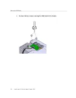
Страница 149: ...sh Drive on page 152 Remove the USB flash drive as part of another component s service operation Remove the USB Flash Drive on page 150 Install the USB flash drive as part of another component s service operation Install the USB Flash Drive on page 152 Related Information Identifying Components on page 13 Detecting and Managing Faults on page 21 Component Service Task Reference on page 65 Preparin...

Страница 150: ...move the USB Flash Drive on page 150 Front Panel LEDs on page 31 Rear Panel LEDs on page 33 Remove the USB Flash Drive Removing the USB flash drive is a cold service operation You must power off the server before you remove the USB flash drive 1 Consider your first step If you have not prepared for service do so now See Preparing for Service on page 61 If you are removing the USB flash drive as pa...

Страница 151: ...sh Drive on page 152 If you removed the USB flash drive as part of another component s removal or installation procedure return to that procedure See Component Service Task Reference on page 65 for assistance Otherwise go to Step 5 5 Finish the removal procedure See Returning the Server to Operation on page 247 Related Information Install the USB Flash Drive on page 152 Preparing for Service on pa...

Страница 152: ... drive as part of another component s removal or installation procedure go to Step 2 If you are installing a new USB flash drive go to Step 2 2 Position the USB flash drive to where it installs onto the motherboard The USB flash drive installs into the USB socket that is near the middle of the motherboard The socket is labeled USB 0 See Component Locations Motherboard Memory and PCIe Cards on page...

Страница 153: ...onent Service Task Reference on page 65 for assistance If you installed a new USB flash drive go to Step 5 5 Finish the installation procedure See Returning the Server to Operation on page 247 Related Information Remove the USB Flash Drive on page 150 Preparing for Service on page 61 Returning the Server to Operation on page 247 Servicing the USB Flash Drive 153 ...

Страница 154: ...154 Netra Server X5 2 Service Manual October 2016 ...
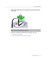
Страница 155: ...3 Remove the DVD SATA Cable on page 164 Install the DVD SATA Cable on page 166 Remove the PDB Signal Cable on page 167 Install the PDB Signal Cable on page 169 Remove a system cable as part of another component s service operation Remove the SAS Drive Signal Cable on page 157 Remove the Backplane Data Cable on page 159 Remove the Backplane Power Cable on page 161 Remove the DVD SATA Cable on page ...

Страница 156: ...ask Reference on page 65 Preparing for Service on page 61 Returning the Server to Operation on page 247 System Cable Configuration This illustration identifies system cables routed throughout the chassis interior No Description Links 1 PDB signal cable Remove the PDB Signal Cable on page 167 156 Netra Server X5 2 Service Manual October 2016 ...

Страница 157: ...to the Oracle 1 6TB NVMe SSD Documentation Library 8 LED board cable Remove the LED Board on page 212 Install the LED Board on page 215 9 SAS 0 3 drive signal cable Remove the SAS Drive Signal Cable on page 157 Install the SAS Drive Signal Cable on page 158 10 NVMe A drive cable optional Refer to the Oracle 1 6TB NVMe SSD Documentation Library Related Information Component Locations Storage Power ...

Страница 158: ...omponent s removal or installation procedure return to that procedure See Component Service Task Reference on page 65 for assistance Related Information Install the SAS Drive Signal Cable on page 158 Component Locations Storage Power and Fan Modules on page 14 Preparing for Service on page 61 Returning the Server to Operation on page 247 Install the SAS Drive Signal Cable Installing a cable is a c...

Страница 159: ...ce Task Reference on page 65 for assistance 7 Finish the installation procedure See Returning the Server to Operation on page 247 Related Information Remove the SAS Drive Signal Cable on page 157 Component Locations Storage Power and Fan Modules on page 14 Preparing for Service on page 61 Returning the Server to Operation on page 247 Remove the Backplane Data Cable Removing a cable is a cold servi...

Страница 160: ...nt Service Task Reference on page 65 for assistance Related Information Install the Backplane Data Cable on page 160 Component Locations Storage Power and Fan Modules on page 14 Preparing for Service on page 61 Returning the Server to Operation on page 247 Install the Backplane Data Cable Installing a cable is a cold service operation You must power off the server before installing the cable 1 Con...

Страница 161: ...ning the Server to Operation on page 247 Related Information Remove the Backplane Data Cable on page 159 Component Locations Storage Power and Fan Modules on page 14 Preparing for Service on page 61 Returning the Server to Operation on page 247 Remove the Backplane Power Cable Removing a cable is a cold service operation You must power off the server before you remove the cable 1 Determine the loc...

Страница 162: ...d connector 7 Set the cable aside 8 Consider your next step If you removed a cable as part of a replacement operation install a new cable See Install the Backplane Power Cable on page 163 If you removed a cable as part of another component s removal or installation procedure return to that procedure See Component Service Task Reference on page 65 for assistance Related Information Install the Back...

Страница 163: ...der your first step If you are replacing a cable remove the faulty or obsolete cable first then return to this procedure Step 2 See Remove the Backplane Power Cable on page 161 If you are installing a cable as part of another component s removal or installation procedure go to Step 2 2 Connect the backplane power cable to the motherboard connector 3 Route the cable into the cable clamp and against...

Страница 164: ...247 Related Information Remove the Backplane Power Cable on page 161 Component Locations Storage Power and Fan Modules on page 14 Preparing for Service on page 61 Returning the Server to Operation on page 247 Remove the DVD SATA Cable Removing a cable is a cold service operation You must power off the server before you remove the cable 1 Determine which cable to remove See System Cable Configurati...

Страница 165: ...ext step If you removed the cable as part of a replacement operation install a new cable See Install the DVD SATA Cable on page 166 If you removed the cable as part of another component s removal or installation procedure return to that procedure See Component Service Task Reference on page 65 for assistance Related Information Install the DVD SATA Cable on page 166 Component Locations Storage Pow...

Страница 166: ... faulty or obsolete cable first then return to this procedure Step 2 See Remove the DVD SATA Cable on page 164 If you are installing a cable as part of another component s removal or installation procedure go to Step 2 2 Connect the DVD SATA cable to the motherboard connector 3 Route the DVD SATA cable to the drive backplane 4 Review this information and complete these prerequisites in this order ...

Страница 167: ...ion Remove the DVD SATA Cable on page 164 Component Locations Storage Power and Fan Modules on page 14 Preparing for Service on page 61 Returning the Server to Operation on page 247 Remove the PDB Signal Cable Removing a cable is a cold service operation You must power off the server before you remove the cable 1 Determine which cable to remove See System Cable Configuration on page 156 2 Consider...

Страница 168: ...d the cable as part of a replacement operation install a new cable See Install the PDB Signal Cable on page 169 If you removed the cable as part of another component s removal or installation procedure return to that procedure See Component Service Task Reference on page 65 for assistance Related Information Install the PDB Signal Cable on page 169 Component Locations Storage Power and Fan Modules...

Страница 169: ...l Cable on page 167 If you are installing a cable as part of another component s removal or installation procedure go to Step 2 2 Connect the PDB signal cable to the motherboard connector and the PDB 3 Review this information and complete these prerequisites in this order Install the PSU Duct on page 248 Install the Air Duct on page 249 Secure the Drive Cage on page 253 Install the Fan Tray on pag...

Страница 170: ...return to that procedure See Component Service Task Reference on page 65 for assistance 5 Finish the installation procedure See Returning the Server to Operation on page 247 Related Information Remove the PDB Signal Cable on page 167 Component Locations Storage Power and Fan Modules on page 14 Preparing for Service on page 61 Returning the Server to Operation on page 247 170 Netra Server X5 2 Serv...

Страница 171: ...t s service operation Remove the Drive Backplane on page 173 Install the drive backplane as part of another component s service operation Install the Drive Backplane on page 176 Determine if the drive backplane is faulty Determine if the Drive Backplane Is Faulty on page 172 Detecting and Managing Faults on page 21 Related Information Identifying Components on page 13 Detecting and Managing Faults...

Страница 172: ...2 Determine if the Drive Backplane Is Faulty You must determine if the drive backplane is faulty before you replace it 1 Check to see if any System Service Required LEDs are lit or flashing See Interpreting Diagnostic LEDs on page 30 2 In Oracle ILOM check the health of the storage system show System Storage System Power Targets Disks Controllers Volumes Expanders Properties health OK health_detai...

Страница 173: ... is faulty seek further information See Detecting and Managing Faults on page 21 Related Information Remove the Drive Backplane on page 173 Drive Backplane Configuration on page 171 Verify the Drive Backplane on page 178 Detecting and Managing Faults on page 21 Remove the Drive Backplane Removing the drive backplane is a cold service operation You must power off the server before you remove the dr...

Страница 174: ... page 113 Remove a Fan Module on page 132 Remove all fan modules Remove the Fan Tray on page 80 Rotate the Drive Cage to the Service Position on page 82 3 Loosen the five screws from the drive backplane 174 Netra Server X5 2 Service Manual October 2016 ...
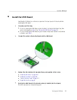
Страница 175: ...e See Install the Drive Backplane on page 176 If you removed the drive backplane as part of another component s removal or installation procedure return to that procedure See Component Service Task Reference on page 65 for assistance Related Information Determine if the Drive Backplane Is Faulty on page 172 Install the Drive Backplane on page 176 Preparing for Service on page 61 Returning the Serv...

Страница 176: ...ve backplane first then return to this procedure Step 2 See Remove the Drive Backplane on page 173 If you are installing the drive backplane as part of another component s removal or installation procedure go to Step 2 2 Position the drive backplane to where it will install into the chassis The drive backplane aligns with the drive connectors down The two alignment holes are on the left and the si...

Страница 177: ...llation procedure return to that procedure See Component Service Task Reference on page 65 for assistance 5 Review this information and complete these prerequisites in this order Secure the Drive Cage on page 253 Install the Fan Tray on page 255 Install a Fan Module on page 133 Install all fan modules Install the DVD Drive on page 116 Install a SAS Drive on page 99 Install all drives Install the F...

Страница 178: ...plane After you install the drive backplane you can verify its functionality 1 Access Oracle ILOM See Access the SP Oracle ILOM on page 28 2 Reset the drive backplane set SYS DBP clear_fault_action true Are you sure you want to clear SYS DBP y n y Set clear_fault_action to true 3 Verify that the drive backplane is no longer considered faulty then return to this procedure See Determine if the Drive...

Страница 179: ...Verify the Drive Backplane Drive Backplane Configuration on page 171 Determine if the Drive Backplane Is Faulty on page 172 Servicing the Drive Backplane 179 ...

Страница 180: ...180 Netra Server X5 2 Service Manual October 2016 ...
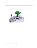
Страница 181: ... page 190 Verify a DIMM on page 193 Remove a DIMM as part of another component s service operation Remove a DIMM on page 187 Install a DIMM as part of another component s service operation Install a DIMM on page 190 Add additional DIMMs DIMM Configuration on page 182 Install a DIMM on page 190 Verify a DIMM on page 193 Decrease the number of existing DIMMs Remove a DIMM on page 187 Identify a faul...

Страница 182: ... the far left has the Oracle ILOM legacy target of SYS MB P1 D0 This same slot has the Oracle ILOM System target of System Memory DIMMs DIMM_0 Note This illustration shows the DIMM slots for the dual processor configuration With the single processor configuration the DIMM slots on P1 are not functional and must be filled with filler panels Number Oracle ILOM Target 1 SYS MB P0 D 0 5 2 SYS MB P0 D ...

Страница 183: ...tall a DIMM filler With the single processor configuration all DIMM slots on P1 must be filled with filler panels Caution Overheating hazard There must be no empty DIMM slots Populate the DIMMs in the order described in DIMM Population Guidelines for Dual Processor Servers on page 184 Related Information DIMM Population Guidelines for Dual Processor Servers on page 184 Install a DIMM on page 190 L...

Страница 184: ...plastic for the main body of the socket and the ejector latches and are in three combinations to distinguish them as an aide for installation order Fill the sockets in this order 1 Fill all black sockets with black ejectors black black 2 Fill the black sockets with white ejectors black white 3 Fill the white sockets with white ejectors white white Install DIMMs into DIMM sockets starting with P0 D...

Страница 185: ...eplace it 1 Check to see if any System Service Required LEDs are lit or flashing See Interpreting Diagnostic LEDs on page 30 2 In Oracle ILOM check the health of the memory system show System Memory System Memory Targets Properties health OK health_details If the health_details property identifies a faulty DIMM replace it See Remove a DIMM on page 187 Servicing DIMMs 185 ...

Страница 186: ... 0 to 23 If the health_details property identifies the DIMM as faulty or the DIMM cannot be identified replace it See Remove a DIMM on page 187 5 Verify that a DIMM is faulty If a DIMM is faulty you will see SYS MB Px Dy under the Value heading where x is 0 or 1 y is 0 to 11 For example show faulty Target Property Value SP faultmgmt 0 fru SYS MB P0 D7 If a DIMM is faulty replace it See Remove a DI...

Страница 187: ...aging Faults on page 21 Remove a DIMM Removing a DIMM is a cold service operation You must power off the server before you remove the DIMM 1 Determine which DIMM to remove See Locate a Faulty DIMM on page 185 2 Consider your next step If you have not prepared for service do so now See Preparing for Service on page 61 If you are removing a DIMM as part of another component s removal or installation...

Страница 188: ...Remove a DIMM 5 Press down and out on the release levers at both ends of the DIMM slot 188 Netra Server X5 2 Service Manual October 2016 ...

Страница 189: ...tion install a new DIMM See Install a DIMM on page 190 If you removed a DIMM as part of another component s removal or installation procedure return to that procedure See Component Service Task Reference on page 65 for assistance If you are not replacing the DIMM install a DIMM filler in its place See Install a DIMM on page 190 Caution Overheating hazard There must be no empty DIMM slots Servicing...

Страница 190: ... faulty or obsolete DIMM first then return to this procedure Step 3 See Remove a DIMM on page 187 If you are installing a new or an additional DIMM go to Step 2 If you are installing a DIMM as part of another component s removal or installation procedure go to Step 3 2 Review this information and complete these prerequisites in this order DIMM Configuration on page 182 Preparing for Service on pag...

Страница 191: ...Install a DIMM 4 Align the DIMM to the location where it installs into the slot Ensure that the notch in the DIMM lines up with the key in the slot Servicing DIMMs 191 ...

Страница 192: ...you installed a DIMM as part of another component s removal or installation procedure return to that procedure See Component Service Task Reference on page 65 for assistance If you have installed a new DIMM go to Step 8 8 Review this information and complete these prerequisites in this order Install the Air Duct on page 249 Secure the Drive Cage on page 253 9 Complete these postrequisites in this ...

Страница 193: ...2 Reset the DIMM set SYS MB Px Dy clear_fault_action true Are you sure you want to clear SYS MB P0 D7 y n y Set clear_fault_action to true 3 Consider your next step If you installed a new DIMM as part of a replacement operation verify that the DIMM is no longer considered faulty then return to this procedure See Locate a Faulty DIMM on page 185 If you installed a new DIMM to increase functionality...

Страница 194: ...ed show System Memory DIMMs DIMM_x where x is the slot number where the DIMM is installed Related Information Install a DIMM on page 190 DIMM Configuration on page 182 Locate a Faulty DIMM on page 185 194 Netra Server X5 2 Service Manual October 2016 ...

Страница 195: ...vice the CPUs CPU Configuration on page 195 Locate a Faulty CPU on page 196 Remove a CPU on page 198 Install a CPU on page 203 Related Information Identifying Components on page 13 Detecting and Managing Faults on page 21 Component Service Task Reference on page 65 Preparing for Service on page 61 Returning the Server to Operation on page 247 CPU Configuration This illustration shows the locations...

Страница 196: ... LEDs on page 30 2 In Oracle ILOM check the health of the CPUs Replace x with 0 or 1 in the dual processor configuration The CPU is always CPU_0 in the single processor configuration show System Processors CPUs CPU_x System Processors CPUs CPU_0 Targets Properties health Service Required 3 Run the show faulty command See Display Faults show faulty Command on page 47 196 Netra Server X5 2 Service M...

Страница 197: ...minDiag docs for information 6 If you are unable to determine if a CPU is faulty seek further information See Detecting and Managing Faults on page 21 Related Information Remove a CPU on page 198 CPU Configuration on page 195 Detecting and Managing Faults on page 21 CPU Tool When you remove and install a CPU a special tool is required for safe handling of the CPU The CPU tool is provided in the CP...

Страница 198: ...ider your next step If you have not prepared for service do so now See Preparing for Service on page 61 If you are removing a CPU as part of another component s removal or installation procedure go to Step 3 3 Review this information and complete these prerequisites in this order Rotate the Drive Cage to the Service Position on page 82 Remove the Air Duct on page 83 4 Locate the CPU to remove See ...

Страница 199: ... the heat sink to the CPU Caution Do not pull forcibly as you might damage the heat sink or CPU socket 7 Use an alcohol pad to clean the thermal compound from the heat sink and CPU Note Be careful not to get the thermal compound on your fingers because this could contaminate components 8 Unhook the pressure frame release levers from the catches of the CPU socket and raise them upward to approximat...

Страница 200: ... lowering the right release lever and lifting the pressure frame up to the fully open position 10 Press the release button on the CPU tool 11 Position the tool over the CPU socket and lower it onto the CPU 200 Netra Server X5 2 Service Manual October 2016 ...

Страница 201: ...Remove a CPU The triangle on the side of the tool aligns with pin 1 of the CPU 12 Push the hold lever outward to engage the CPU You hear a click and the release button retracts Servicing CPUs 201 ...

Страница 202: ...sp the tool by its sides and lift it from the CPU socket 14 While holding the tool upside down with one hand and the CPU edges with the other hand press the release button 202 Netra Server X5 2 Service Manual October 2016 ...

Страница 203: ...03 Preparing for Service on page 61 Returning the Server to Operation on page 247 Install a CPU Installing a CPU is a cold service operation You must power off the server before installing the CPU 1 Review this information and complete these prerequisites in this order if you have not done so already Rotate the Drive Cage to the Service Position on page 82 Remove the Air Duct on page 83 2 Unpack t...

Страница 204: ...uring clips See CPU Tool on page 197 4 Turn the tool upside down and lower the CPU into the tool pin side up The triangle on the side of the tool aligns with pin 1 of the CPU 5 Press the hold lever outward to engage the CPU 204 Netra Server X5 2 Service Manual October 2016 ...

Страница 205: ...ver the CPU socket and lower it into place The triangle on the side of the tool aligns with pin 1 of the CPU socket Caution The tool must be level and flat onto the socket not offset or angled 7 Press the release button on the tool to release the CPU into the socket Servicing CPUs 205 ...

Страница 206: ...o not attempt to forcibly seat the CPU 8 Remove the tool The processor should lie flat in the socket and be properly aligned 9 Lower the pressure frame to the closed position 206 Netra Server X5 2 Service Manual October 2016 ...

Страница 207: ...me should sit flat over the processor 10 Lower the release levers and hook them under the catches of the CPU socket 11 Use the syringe to apply approximately 0 1 ml of thermal compound to the top center of the CPU Servicing CPUs 207 ...

Страница 208: ...e server Caution Moving the heat sink too much unevenly distributes the thermal compound and can lead to CPU damage 13 Tighten the four captive screws of the CPU heat sink Alternate between the screws in an X pattern turning each one half revolution until they are fully seated 14 Review this information and complete these postrequisites in this order Install the Air Duct on page 249 208 Netra Serv...

Страница 209: ...erver to Operation on page 247 16 Verify the functionality of the CPUs by checking for faults See Locate a Faulty CPU on page 196 Related Information Remove a CPU on page 198 CPU Configuration on page 195 Preparing for Service on page 61 Returning the Server to Operation on page 247 Servicing CPUs 209 ...

Страница 210: ...210 Netra Server X5 2 Service Manual October 2016 ...

Страница 211: ... another component s service operation Remove the LED Board on page 212 Install the LED board as part of another component s service operation Install the LED Board on page 215 Determine if the LED board is faulty Determine if the LED Board Is Faulty on page 211 Detecting and Managing Faults on page 21 Related Information Identifying Components on page 13 Detecting and Managing Faults on page 21 C...

Страница 212: ...ove the LED Board Removing the LED board is a cold service operation You must power off the server before you remove the LED board 1 Consider your first step If you have not prepared for service do so now See Preparing for Service on page 61 If you are removing the LED board as part of another component s removal or installation procedure go to Step 2 2 Review this information and complete these p...

Страница 213: ...Remove the LED Board 3 Disconnect the cable from the motherboard 4 Remove the two screws securing the LED assembly to the chassis Servicing the LED Board 213 ...

Страница 214: ...rd 5 Lift the LED assembly from the chassis 6 Remove the two screws securing the LED board to the LED assembly 7 Lift the LED board from the LED assembly and set it aside 214 Netra Server X5 2 Service Manual October 2016 ...

Страница 215: ...oard Is Faulty on page 211 Install the LED Board on page 215 Preparing for Service on page 61 Returning the Server to Operation on page 247 Install the LED Board Installing the LED board is a cold service operation You must power off the server before installing the LED board 1 Consider your first step If you are replacing the LED board remove the faulty or obsolete LED board first then return to ...

Страница 216: ...l the LED Board 2 Set the LED board into the LED assembly 3 Install and tighten the two screws 4 Position the LED assembly over the flange on the chassis left 216 Netra Server X5 2 Service Manual October 2016 ...

Страница 217: ...two screws 6 Route the cable into the cable clamp and against the chassis wall 7 Connect the cable to the motherboard 8 Consider your next step If you installed the LED board as part of a replacement operation go to Step 9 Servicing the LED Board 217 ...

Страница 218: ...o finish the installation procedure Returning the Server to Operation on page 247 Verify the LED Board on page 218 Related Information Remove the LED Board on page 212 Verify the LED Board on page 218 Preparing for Service on page 61 Returning the Server to Operation on page 247 Verify the LED Board After you install the LED board you can verify its functionality Press and hold the Locator button ...

Страница 219: ...ration Install the USB Board on page 223 Related Information Identifying Components on page 13 Detecting and Managing Faults on page 21 Component Service Task Reference on page 65 Preparing for Service on page 61 Returning the Server to Operation on page 247 Remove the USB Board Removing the USB board is a cold service operation You must power off the server before you remove the USB board 1 Consi...

Страница 220: ...Remove the USB Board 2 Remove the two screws securing the USB board to the chassis 220 Netra Server X5 2 Service Manual October 2016 ...

Страница 221: ...and allow the USB board to float freely Note Do not disconnect the cable from the USB board 4 Review this information and complete these prerequisites in this order Remove the Filter on page 89 Rotate the Drive Cage to the Service Position on page 82 Servicing the USB Board 221 ...

Страница 222: ...ration install a new USB board See Install the USB Board on page 223 If you removed the USB board as part of another component s removal or installation procedure return to that procedure See Component Service Task Reference on page 65 for assistance Related Information Install the USB Board on page 223 Preparing for Service on page 61 Returning the Server to Operation on page 247 222 Netra Server...

Страница 223: ...on page 219 If you are installing the USB board as part of another component s removal or installation procedure go to Step 4 2 Connect the cable to the motherboard and the USB board 3 Review this information and complete these prerequisites in this order Install the PSU Duct on page 248 Install the Air Duct on page 249 Secure the Drive Cage on page 253 Install the Filter on page 91 4 Position the...

Страница 224: ...Install the USB Board 5 Lower the USB board to the chassis and slide it forward over the alignment pin 224 Netra Server X5 2 Service Manual October 2016 ...

Страница 225: ...led the USB board as part of another component s removal or installation procedure return to that procedure See Component Service Task Reference on page 65 for assistance 8 Finish the installation procedure See Returning the Server to Operation on page 247 Related Information Remove the USB Board on page 219 Preparing for Service on page 61 Returning the Server to Operation on page 247 Servicing t...

Страница 226: ...226 Netra Server X5 2 Service Manual October 2016 ...

Страница 227: ...ove the Motherboard on page 230 Install the motherboard as part of another component s service operation Install the Motherboard on page 233 Determine if the motherboard is faulty Determine if the Motherboard Is Faulty on page 227 Detecting and Managing Faults on page 21 Related Information Identifying Components on page 13 Detecting and Managing Faults on page 21 Component Service Task Reference ...

Страница 228: ... CPU_0 Targets Properties health OK health_details where x is the number of the CPU either 0 or 1 If the health_details property identifies the CPU as faulty replace the motherboard See Remove the Motherboard on page 230 4 Check the health of the networking system show System Networking System Networking Targets Ethernet_NICs Properties health OK health_details If the health_details property ident...

Страница 229: ... on page 230 If a FRU value different from SYS MB SYS MB P0 or SYS MB P1 is displayed see Component Service Task Reference on page 65 to identify which component is faulty 7 Use the Oracle ILOM faultmgmt shell to identify the faulty component See Display Faults faultmgmt Shell on page 48 Check the Fault class and Description fields for more information If the motherboard is faulty replace it See R...

Страница 230: ...ce do so now See Preparing for Service on page 61 If you are removing the motherboard as part of another component s removal or installation procedure go to Step 2 2 Review this information and complete these prerequisites in this order Remove the Filter on page 89 Remove a Fan Module on page 132 Remove all fan modules Remove the Fan Tray on page 80 Rotate the Drive Cage to the Service Position on...

Страница 231: ...otherboard and move them out of the way 4 Remove the four bus bar screws 5 Fully loosen the two captive screws at the front of the motherboard 6 Grasp the two motherboard handles and slide the motherboard forward off of the alignment pins Servicing the Motherboard 231 ...

Страница 232: ...ee Install the Motherboard on page 233 If you removed the motherboard as part of another component s removal or installation procedure return to that procedure See Component Service Task Reference on page 65 for assistance Related Information Determine if the Motherboard Is Faulty on page 227 Install the Motherboard on page 233 Preparing for Service on page 61 Returning the Server to Operation on ...

Страница 233: ...move the Motherboard on page 230 If you are installing the motherboard as part of another component s removal or installation procedure go to Step 2 2 Position the motherboard for installation into the chassis The heatsinks are toward the front of the chassis and the ports are at the rear 3 Lift the motherboard by the handles and slowly move the motherboard rearward until the connectors slighty pr...

Страница 234: ...the four holes in the bus bars 7 Tighten the captive screw 8 Install and tighten the four bus bar screws 9 Reconnect the cables you previously disconnected 10 Consider your next step If you installed the motherboard as part of a replacement operation go to Step 11 If you installed the motherboard as part of another component s removal or installation procedure return to that procedure See Componen...

Страница 235: ...e Server to Operation on page 247 Verify the Motherboard on page 235 Related Information Remove the Motherboard on page 230 Verify the Motherboard on page 235 Preparing for Service on page 61 Returning the Server to Operation on page 247 Verify the Motherboard After you install the motherboard you can verify its functionality 1 Access Oracle ILOM See Access the SP Oracle ILOM on page 28 2 Reset th...

Страница 236: ...power currently consumed show SYS VPS value SYS VPS Properties value 159 175 Watts Related Information Install the Motherboard on page 233 Determine if the Motherboard Is Faulty on page 227 236 Netra Server X5 2 Service Manual October 2016 ...

Страница 237: ... operation Remove the PDB on page 239 Install the PDB as part of another component s service operation Install the PDB on page 242 Determine if the PDB is faulty Determine if the PDB Is Faulty on page 237 Detecting and Managing Faults on page 21 Related Information Identifying Components on page 13 Detecting and Managing Faults on page 21 Component Service Task Reference on page 65 Preparing for S...

Страница 238: ...he PDB on page 239 If a FRU value different from SYS PDB is displayed see Component Service Task Reference on page 65 to identify which component is faulty 4 Use the Oracle ILOM faultmgmt shell to identify the faulty component See Display Faults faultmgmt Shell on page 48 Check the Fault class and Description fields for more information If the PDB is faulty replace it See Remove the PDB on page 23...

Страница 239: ...e Preparing for Service on page 61 If you are removing the PDB as part of another component s removal or installation procedure go to Step 2 2 Review this information and complete these prerequisites in this order Remove a Power Supply on page 122 Remove both power supplies Remove the Filter on page 89 Remove a Fan Module on page 132 Remove all fan modules Remove the Fan Tray on page 80 Rotate the...

Страница 240: ...Remove the PDB 3 Disconnect the cable from the PDB 4 Remove the four screws securing the PDB bus bars to the motherboard 240 Netra Server X5 2 Service Manual October 2016 ...

Страница 241: ...Remove the PDB 5 Loosen the two screws securing the PDB to the chassis 6 Lift the PDB bus bars out from under the motherboard and remove the PDB from the chassis Servicing the PDB 241 ...

Страница 242: ...B on page 242 Preparing for Service on page 61 Returning the Server to Operation on page 247 Install the PDB Installing the PDB is a cold service operation You must power off the server before installing the PDB 1 Consider your first step If you are replacing the PDB remove the faulty or obsolete PDB first then return to this procedure Step 2 See Remove the PDB on page 239 If you are installing th...

Страница 243: ...Install the PDB 3 Place the bus bars into the channels under the motherboard and align the PDB with two posts for the captive screw 4 Tighten the two captive screws Servicing the PDB 243 ...

Страница 244: ...Install the PDB 5 Install the four screws securing the PDB bus bars to the motherboard 6 Reconnect the cable to the PDB 244 Netra Server X5 2 Service Manual October 2016 ...

Страница 245: ... the USB Flash Drive on page 152 Secure the Drive Cage on page 253 Install the Fan Tray on page 255 Install a Fan Module on page 133 Install all fan modules 9 Complete these postrequisites in this order to finish the installation procedure Returning the Server to Operation on page 247 Verify the PDB on page 245 Related Information Remove the PDB on page 239 Verify the PDB on page 245 Preparing for...

Страница 246: ...procedure See Determine if the PDB Is Faulty on page 237 4 Verify that the PDB is reporting temperatures show SYS PDB T_IN_PS value SYS PDB T_IN_PS Properties value 23 500 degree C Related Information Install the PDB on page 242 Determine if the PDB Is Faulty on page 237 246 Netra Server X5 2 Service Manual October 2016 ...

Страница 247: ... Step 3 or these components Drive signal cable Drive power cable DVD SATA cable Install the Fan Tray on page 255 5 Install the top cover if you serviced the components in Step 1 Step 2 Step 3 Step 4 or these components Fan modules PCIe cards Battery USB flash drive Install the Top Cover on page 257 6 Install the server into the rack See Netra Server X5 2 Installation Guide install the server into ...

Страница 248: ...n Module on page 136 Verify a PCIe Card on page 142 Verify a SAS Drive on page 101 Verify a Power Supply on page 126 Related Information Identifying Components on page 13 Detecting and Managing Faults on page 21 Preparing for Service on page 61 Install the PSU Duct Perform this task when you have previously removed the PSU duct 248 Netra Server X5 2 Service Manual October 2016 ...

Страница 249: ...ation procedure return to that procedure See Component Service Task Reference on page 65 for assistance Otherwise install the air duct See Install the Air Duct on page 249 Related Information Remove the PSU Duct on page 87 Install the Air Duct on page 249 Install the Air Duct Perform this task when you have previously removed the air duct 1 If you previously removed the PSU duct install it Returni...

Страница 250: ...uct on page 248 2 Move any loose cables to the gap between the DIMMs and the chassis walls 3 Align the air duct to where it installs into the chassis 4 Lower the air duct onto the alignment pins 250 Netra Server X5 2 Service Manual October 2016 ...

Страница 251: ...Install the Air Duct 5 Set the left L thumbscrew bracket over the alignment pins and slide it rearward Returning the Server to Operation 251 ...

Страница 252: ...nstallation procedure return to that procedure See Component Service Task Reference on page 65 for assistance Otherwise secure the drive cage See Secure the Drive Cage on page 253 Related Information Install the PSU Duct on page 248 Remove the Air Duct on page 83 Secure the Drive Cage on page 253 252 Netra Server X5 2 Service Manual October 2016 ...

Страница 253: ... to the service position 1 If you previously removed the PSU duct or removed the air duct complete these prerequisites as necessary in this order Install the PSU Duct on page 248 Install the Air Duct on page 249 2 Lower the drive cage to the horizontal position Returning the Server to Operation 253 ...

Страница 254: ...e Depending on your server s configuration you might not have the DVD SATA cable 3 as seen in the illustration 5 Install the filter See Install the Filter on page 91 6 Consider your next step If you secured the drive cage as part of another component s removal or installation procedure return to that procedure See Component Service Task Reference on page 65 for assistance Otherwise install the fan...

Страница 255: ...the drive cage complete these prerequisites as necessary in this order Install the PSU Duct on page 248 Install the Air Duct on page 249 Secure the Drive Cage on page 253 2 Move any loose cables so that they are against the chassis walls 3 Align the fan tray to where it installs into the chassis Two arrows on the top of power supply bay show where the fan tray aligns 4 Slowly lower the fan tray in...

Страница 256: ...f another component s removal or installation procedure return to that procedure See Component Service Task Reference on page 65 for assistance Otherwise install the top cover See Install the Top Cover on page 257 Related Information Secure the Drive Cage on page 253 Remove the Fan Tray on page 80 Install the Top Cover on page 257 256 Netra Server X5 2 Service Manual October 2016 ...

Страница 257: ... removed the air duct raised the drive cage or removed the fan tray complete these prerequisites as necessary in this order Install the PSU Duct on page 248 Install the Air Duct on page 249 Secure the Drive Cage on page 253 Install the Fan Tray on page 255 Install a Fan Module on page 133 Install all fan modules Returning the Server to Operation 257 ...

Страница 258: ... 2 Position the top cover on the chassis with the front edge of the top cover 0 5 in 13 mm rearward of the front edge of the chassis 3 Slide the top cover forward into place 258 Netra Server X5 2 Service Manual October 2016 ...

Страница 259: ...to the rack Refer to Netra Server X5 2 Installation Guide installing the server into the rack 6 Connect the power cords See Connect Power Cords on page 260 Related Information Install the Fan Tray on page 255 Remove the Top Cover on page 77 Connect Power Cords on page 260 Returning the Server to Operation 259 ...

Страница 260: ...ords to the power supplies Note As soon as the power cords are connected standby power is applied Depending on how the firmware is configured the system might boot at this time For AC power cords For DC power cords 260 Netra Server X5 2 Service Manual October 2016 ...

Страница 261: ...ormation Install the Top Cover on page 257 Disconnect Power Cords and Data Cables on page 70 Power On the Server Oracle ILOM on page 261 Power On the Server Power Button on page 262 Power On the Server Oracle ILOM 1 Access Oracle ILOM See Access the SP Oracle ILOM on page 28 2 Power on the server start System The server powers on and boots Returning the Server to Operation 261 ...

Страница 262: ...he Power button on the front panel See Front Panel Components Service on page 17 for the location of the Power button The server powers on and boots 2 If you want to verify an installed component return to that component s verification procedure See Component Service Task Reference on page 65 for assistance Related Information Connect Power Cords on page 260 Power Off the Server Power Button Grace...

Страница 263: ...utput System C chassis Refers to the server enclosure For server modules refers to the modular system enclosure D DHCP Dynamic Host Configuration Protocol DTE Data terminal equipment E ECC Error correcting code ESD Electrostatic discharge F FRU Field replaceable unit Glossary 263 ...

Страница 264: ...etwork interface card or controller NVMe A specification for accessing solid state drives SSDs attached through the PCI Express PCIe bus NVM is an acronym for non volatile memory which is used in SSDs O Oracle ILOM Oracle Integrated Lights Out Manager Oracle ILOM firmware is preinstalled on a variety of Oracle systems Oracle ILOM enables you to remotely manage your Oracle servers regardless of the...

Страница 265: ...R MGT Serial management port A serial port on the server SP the server module SP and the CMM SP Service processor In the server or server module the SP is a card with its own OS The SP processes Oracle ILOM commands providing lights out management control of the host See host SSD Solid state drive SSH Secure shell U UEFI Unified Extensible Firmware Interface UUID Universal unique identifier Glossa...

Страница 266: ...266 Netra Server X5 2 Service Manual October 2016 ...

Страница 267: ...removing 161 drive signal installing 158 removing 157 DVD SATA installing 166 removing 164 locations 14 PDB signal installing 169 removing 167 cables servicing system 155 system configuration 156 clear_fault_action targets 51 components accessing 71 determining health 43 displaying fan speeds 56 displaying faulty 46 displaying health 44 displaying problematic 42 displaying temperature 55 front pan...

Страница 268: ...cords 70 displaying active power consumption 37 chassis serial number 64 component health 44 fan speeds 56 fault state 52 faults 47 48 faulty components 46 firmware version 40 FRUID 52 LED states 57 logs 35 NET MGT properties 39 PCIe card information 43 power consumed 54 problematic components 42 temperature 55 user sessions 38 voltages 53 drive locations 14 drive backplane configuration 171 deter...

Страница 269: ...managing 21 faulty CPUs 196 DIMMs 185 drive 95 drive backplane 172 fan module 131 LED board 211 motherboard 227 PCIe cards 138 PDB 237 power supply 120 filler panels 64 filter adding 91 installing 91 location 14 removing 89 servicing 89 firmware displaying version 40 front panel components 17 LEDs 31 FRU illustration 14 16 service procedures 65 values 65 FRUID displaying 52 legacy targets 53 G gra...

Страница 270: ...tus 149 legacy targets enabling 35 fault state 53 FRUID 53 LED states 57 power consumption 55 troubleshooting 51 locate the server Service 66 locating faulty CPUs 196 DIMMs 185 drives 95 fan modules 131 PCIe cards 138 power supplies 120 Locator LED location 66 log displaying 35 filters 36 login SP 28 M managing faults 21 messages BIOS 40 motherboard determining faulty 227 installing 233 location 1...

Страница 271: ...ng 67 SP 68 powering on server Power button 262 SP 261 preparing for service 61 to power off the server 67 PSU duct installing 248 location 16 removing 87 R raising drive cage 82 rear panel components 18 LEDs 33 removing air duct 83 backplane data cable 159 backplane power cable 161 battery 145 CPUs 198 DIMMs 187 drive backplane 173 drive signal cable 157 DVD drive 113 DVD SATA cable 164 fan modul...

Страница 272: ...preparing 61 procedures 65 servicing battery 145 DIMMs 181 195 drive backplane 171 DVD drive 113 fan modules 129 filter 89 LED board 211 motherboard 227 PCIe cards 137 PDB 237 power supplies 119 SAS drives 93 system cables 155 USB board 219 USB flash drive 149 shutting down Power button 69 SP 68 SP accessing 28 powering on 261 start SYS command 261 stop SYS command 68 symbols in documentation 62 s...

Страница 273: ...lling 152 location 16 removing 150 servicing 149 status LEDs 149 user sessions displaying 38 V verifying DIMMs 193 drive backplane 178 fan modules 136 LED board 218 motherboard 235 PCIe cards 142 PDB 245 power supplies 126 SAS drives 101 voltage displaying 53 VTS diagnostics 25 273 ...

Страница 274: ...274 Netra Server X5 2 Service Manual October 2016 ...

Отзывы: