I N S T A L L A T I O N I N S T R U C T I O N S
I N S T R U C T I O N S D ' I N S T A L L A T I O N
M O N T A G E A N L E I T U N G
BM-9005
HD Projector Mount
Support pour projecteur
HD
HD-Projektorhalterung
BM-9005U
Страница 1: ...T A L L A T I O N I N S T R U C T I O N S I N S T R U C T I O N S D I N S T A L L A T I O N M O N T A G E A N L E I T U N G BM 9005 HD Projector Mount Support pour projecteur HD HD Projektorhalterung BM 9005U ...
Страница 2: ... properly assembled and installed using the instructions provided WARNING Failure to provide adequate structural strength for this component can result in serious personal injury or damage to equipment It is the installer s responsibility to make sure the structure to which this component is attached can support five times the combined weight of all equipment Reinforce the structure as required be...
Страница 3: ...Allentare il fissaggio Bevestiging losdraaien Desserrez les fixations Hex Head Wrench Llave de cabeza hexagonal Sechskantschlüssel Chave de cabeça sextavada Chiave esagonale Zeskantsleutel Clé à tête hexagonale Adjust Ajustar Einstellen Ajustar Regolare Afstellen Ajuster Open Ended Wrench Llave de boca Gabelschlüssel Chave de bocas Chiave a punte aperte Steeksleutel Clé à fourche 1 2 5 32 included...
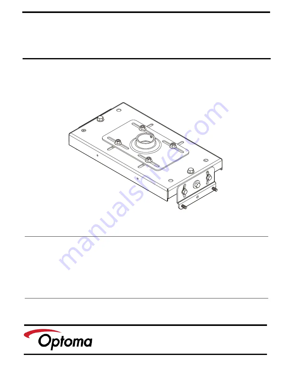
Страница 4: ...e that long edge of BM 9005U mount is located parallel to the screen Siehe Abb 1 2 Tighten the 5 16 18 x 3 8 set screw C into the BM 9005U mount threaded collar to prevent movement of the BM 9005U Siehe Abb 1 Figure 1 3 Proceed to Projector Installation section Installing BM 9005U Mount to LPK 1 Mount Kit 1 Install BM 9005U mount A to LPK 1 low profile mount kit not included following instructions...
Страница 5: ...of mounting hardware may result in personal injury or serious damage to equipment Horizontal Adjustments Siehe Abb 4 1 Loosen but do NOT remove the four nuts holding the top slide bracket on the BM 9005U mount 2 Adjust BM 9005U mount up to 1 1 2 in any direction 3 Tighten the nuts loosened in Step 1 on the top slide bracket Figure 4 Roll Horizontal Tilt Siehe Abb 5 4 Loosen three bolts on each end...
Страница 6: ...levation Siehe Abb 6 7 Loosen two outside bolts on each end of the BM 9005U mount 8 Tilt projector to desired direction 9 Securely tighten two outside bolts on each end of BM 9005U mount Figure 6 x 2 7 9 8 x 2 7 9 Interface bracket and projector not shown ...
Страница 7: ... composants sont correctement montés et installés conformément aux instructions fournies AVERTISSEMENT Une résistance structurelle non appropriée pour ce composant peut entraîner des blessures corporelles graves ou endommager l équipement Il est de la responsabilité de l installateur de s assurer que la structure à laquelle ce composant est attaché peut supporter cinq fois le poids total de l équi...
Страница 8: ...lonne d extension NPT ou à la section Installation du support BM 9005U au kit de montage LPK 1 selon le cas Installation du support BM 9005U à la colonne d extension NPT IMPORTANT Ces instructions d installation supposent qu un tuyau NPT ou NPSM de 1 1 2 aluminium série 40 d une épaisseur minimale de 0 154 ASTM B221 non inclus a été correctement installé et est en place 1 Enfilez le support BM 900...
Страница 9: ... projecteur avec la patte de fixation fournie 1 Orientez le projecteur avec la patte de fixation fournie de manière à ce qu il soit perpendiculaire à l écran Voir la Figure 3 2 Soulevez le projecteur et fixez le aux quatre montants qui s étendent du boîtier Voir la Figure 3 AVERTISSEMENT UNE MAUVAISE INSTALLATION PEUT PROVOQUER UN LA CHUTE DU PROJECTEUR ET ENDOMMAGER CELUI CI VOIRE ENTRAÎNER DES B...
Страница 10: ...ssaire Tournez DANS LE SENS DES AIGUILLES D UNE MONTRE pour relever Tournez DANS LE SENS CONTRAIRE DES AIGUILLES D UNE MONTRE pour abaisser 6 Serrez fermement les trois boulons à chaque extrémité du support BM 9005U Figure 5 Inclinaison élévation verticale Voir la Figure 6 7 Desserrez les deux boulons extérieurs à chaque extrémité du support BM 9005U 8 Inclinez le projecteur dans la direction souh...
Страница 11: ...iert werden WARNUNG Wenn dieses Bauelement nicht an einer Konstruktion mit der erforderlichen Tragfähigkeit montiert wird kann dies zu schweren Verletzungen oder Geräteschäden führen Der Monteur hat dafür zu sorgen dass die Konstruktion an der das Bauelement angebracht wird über die erforderliche Tragfähigkeit verfügt Die Konstruktion muss das fünffache Gesamtgewicht des Geräts tragen können Verst...
Страница 12: ...tage einer VCM Halterung an ein LPK 1 Befestigungsset fort Montage einer BM 9005U Halterung an eine NPT Ausziehsäule WICHTIG Diese Montageanleitungen gehen davon aus dass ein Rohr mit 1 1 2 NPT oder NPSM Gewinde Schedule 40 0 154 Mindestwandstärke aus Aluminium ASTM B221 nicht mitgeliefert ordnungsgemäß montiert und fixiert worden ist 1 Schrauben Sie die BM 9005U Halterung A fest an dasvorhandene ...
Страница 13: ...ehe Abb 2 Abb 2 Montage des Projektors mit der daran befestigten Anschlussplatte 1 Richten Sie den Projektor mit der daran befestigten Anschlussplatte so aus dass er sich im rechten Winkel zur Leinwand befindet Siehe Abb 3 2 Heben Sie den Projektor und befestigen Sie ihn an den vier Stiften die außen aus dem BM 9005U Gehäuse ragen Siehe Abb 3 WARNUNG EINE UNSACHGEMÄSSE MONTAGE KANN ZUM HERUNTERFAL...
Страница 14: ...rseite der BM 9005U Halterung je nach Bedarf Drehen Sie zum Anheben IM UHRZEIGERSINN Drehen Sie zum Absenken GEGEN DEN UHRZEIGERSINN 6 Ziehen Sie die drei Schrauben die sich jeweils an den beiden Enden der BM 9005U Halterung befinden fest an Abb 5 Drehung um die Querachse vertikale Anhebung Siehe Abb 6 7 Lockern Sie die beiden äußeren Schrauben die sich jeweils an den beiden Enden der BM 9005U Hal...
Страница 15: ...Installation Instructions BM 9005U 15 ...
Страница 16: ...BM 9005U Installation Instructions Version 1 0 Optoma Technology http www optoma com us North America Address 47697 Westinghouse Dr Fremont CA 94539 Phone 510 897 8600 1 888 289 6786 ...