


50
HDD to the bottom bracket.
○
4
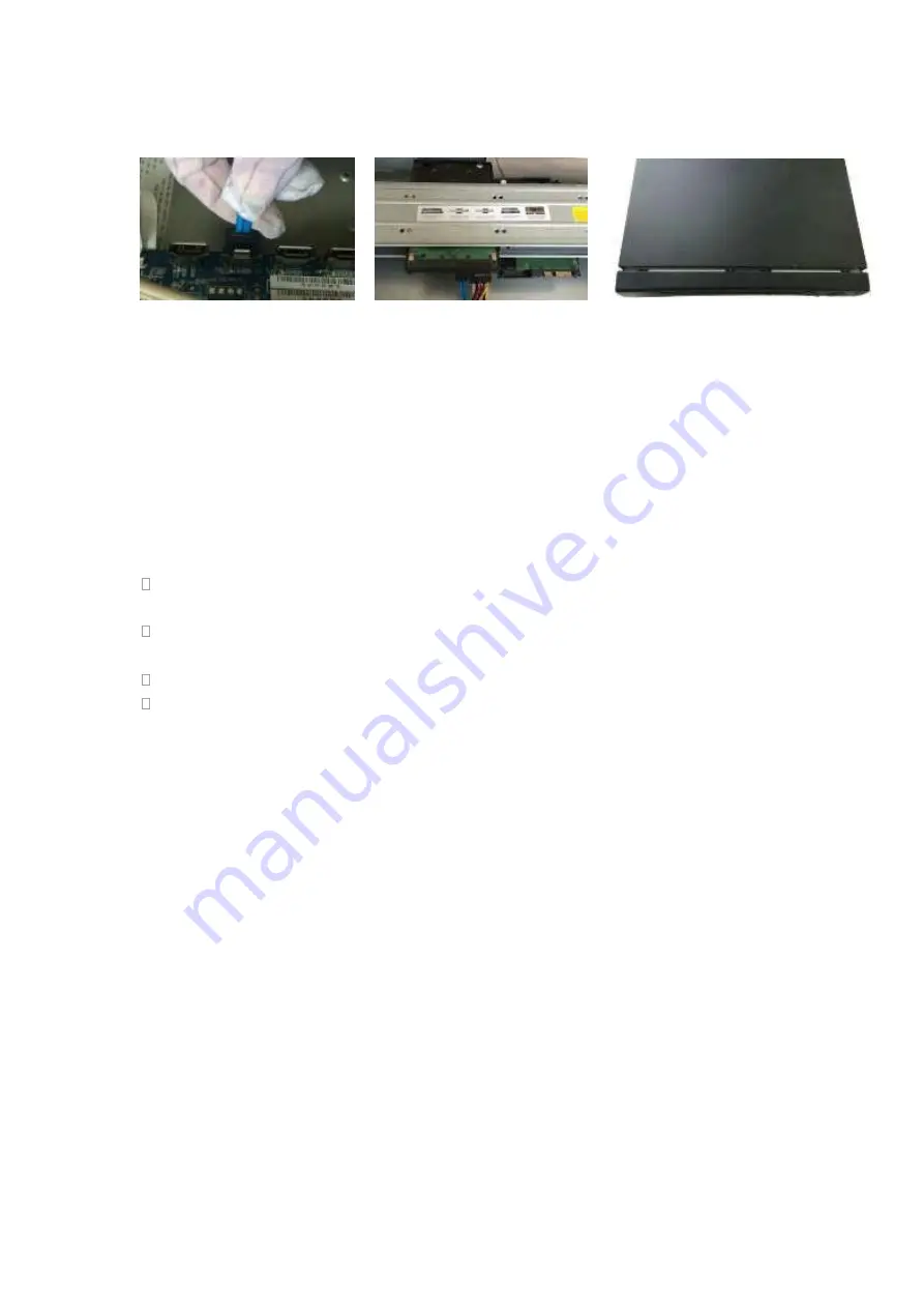
Connect the other end of the
HDD cable to the mainboard.
⑤
Connect the power cable to the
HDD.
⑥
Put the cover back and fix the
screws to secure firmly.
Important:
If the HDD amount is less than four, you do not need to install the HDD bracket.
When there is a bracket, please make sure the installation direction of HDDs is the same.
3.3.7 Rack Installation
The DVR occupies 1.5U/2U rack units of vertical rack space.
Use twelve screws to fix the unit
Please make sure the indoor temperature is below 35
℃
(95°f).
Please make sure there is 15cm (6 inches) space around the device to guarantee
sound ventilation.
Please install from the bottom to the top.
If there are more accessories connected in the rack, please take precaution
measures in case the rack power is overload.
3.4
Connecting Power Supply
Please check input voltage and device power button match or not.
We recommend you use UPS to guarantee steady operation, DVR life span, and other
peripheral equipments operation such as cameras.
3.5
Connecting Video Input and Output Devices
3.5.1 Connecting Video Input
The video input interface is BNC. The input video format includes: PAL/NTSC BNC
(
1.0V
B
P- P
,
B
75Ω.
)
.
The input video format: BNC
(
0.8VP-P
,
75Ω
)
,
The video signal should comply with your national standards.
The input video signal shall have high SNR, low distortion; low interference, natural color
and suitable lightness.
Guarantee the stability and reliability of the camera signal:
The camera shall be installed in a cool, dry place away from direct sunlight, inflammable,
Содержание HDVR161080-Q4
Страница 1: ......
Страница 123: ...308 Figure 4 73 Figure 4 74 ...
Страница 132: ...317 restore original status Figure 4 85 Figure 4 86 4 11 1 3 6 Upgrade Important ...
Страница 156: ...341 Figure 4 109 Figure 4 110 ...
Страница 157: ...342 Figure 4 111 Figure 4 112 ...
Страница 171: ...356 Figure 4 129 Click draw button to draw the zone See Figure 4 130 Figure 4 130 Name Input customized rule name ...
Страница 178: ...363 Figure 4 136 Figure 4 137 ...
Страница 179: ...364 Figure 4 138 Figure 4 139 ...
Страница 182: ...367 Figure 4 142 Figure 4 143 ...
Страница 183: ...368 Figure 4 144 Figure 4 145 ...
Страница 191: ...376 Figure 4 157 Figure 4 158 ...
Страница 209: ...394 Figure 4 180 For digital channel the interface is shown as below See Figure 4 181 Figure 4 181 4 11 5 6 ATM POS ...
Страница 223: ...408 Figure 4 198 ...
Страница 261: ...446 Figure 5 58 Figure 5 59 ...
Страница 275: ...460 Figure 5 75 Figure 5 76 ...
Страница 280: ...465 Figure 5 83 Figure 5 84 Please refer to the following sheet for detailed information ...
Страница 283: ...468 Figure 5 86 Figure 5 87 Figure 5 88 Please refer to the following sheet for detailed information ...
Страница 326: ...511 448K 196M 512K 225M 640K 281M 768K 337M 896K 393M 1024K 450M 1280K 562M 1536K 675M 1792K 787M 2048K 900M ...


