User Manual – ePX 200
OptiPro Systems, LLC.
Page 54 of 60
Last Modified: 7/30/2014
10.1.4
Spindles align (X- and Y-Axis Alignments)
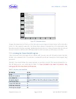
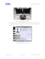
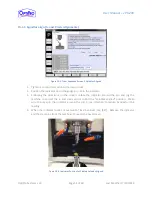
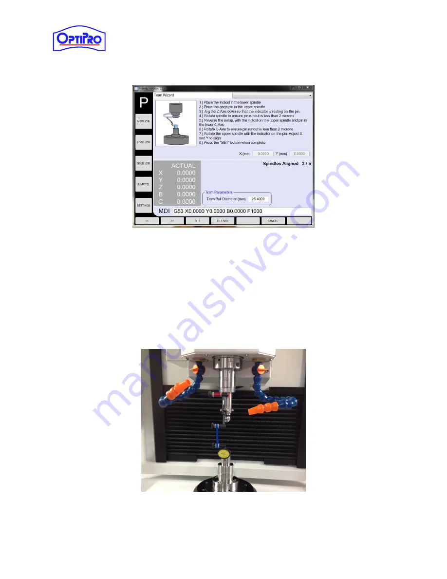
Figure 10-5: Tram Sequence Screen 2, Spindles Aligned
1.
Tighten a second tram pin into the lower chuck.
2.
Position the indicator tip on the gauge pin. Zero the indicator.
3.
Following the directions on the screen, rotate the indicator around the pin and jog the
machine to correct the x- and y-axis errors to find the “spindles aligned” position. Make
sure to only spin the indicator around the pin in one direction to reduce backlash in the
reading.
4.
When the indicator reads a movement of less than 6µm, tap [SET]. Remove the indicator
and the tram pins from the machine. Move to the next screen.
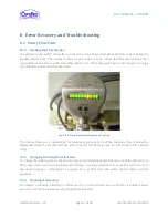
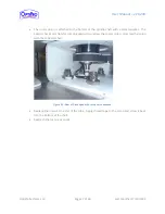
Figure 10-6: Indicator Position for Finding Spindles Aligned

