


OPTIMUM
M A S C H I N E N - G E R M A N Y
Version 1.0.1 2014-05-16
Page 119
Original operating instructions
TU2506 | TU2506V | TU2807 | TU2807V
GB
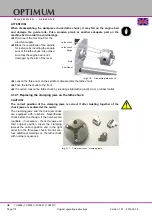
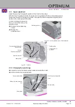
Swing the quadrant to the left until the gearwheels have engaged again.
Re-adjust gear flank clearance by inserting a normal sheet of paper as an adjusting or dis-
tance aid between the gearwheels.
Immobilise the quadrant with the locking screw.
Attach the protective cover of the headstock and reconnect the machine to the power sup-
ply.
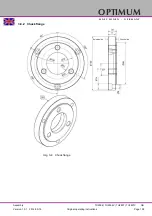
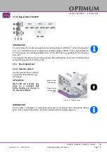
3.14.3 Arrangement of change gears
Img.3-19: arrangement of change gears
3.14.4 Tables for thread-cutting
INFORMATION
The tables for thread-cutting is located on the machine.
The tables are built up in a way that you may later on assemble the required combination to cut
a thread without having to look up the details. Ligature as orientation for the caming of one
toothed wheel to the following one. The identifier "H" stands for bushing or a small toothed
wheel as an auxiliary distance. This smaller toothed wheel as an auxiliary distance must of
course not be camed in with any other toothed wheel.
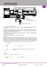
3.14.5 Transmission ratio
The gear transmission ratio is the ratio of the driving toothed wheels to the driven toothed
wheels.
Example calculation for a thread of 0.75 mm on lathe TU2506:
Example calculation for a thread of 0.75 mm on lathe TU2807:
Example calculation for a infeed of 0.09 mm on lathe TU2506:
Z1
Z2
Z4
Z3
L
Lead screw 3 mm pitch
1. change gear (drive unit)
with 40 teeth, standard
i
3xVgx
40x
Z
2x
Z
4
Z
2x
Z
3xL
----------------------------
3x0 5
x
40x45x60
45x80x60
-------------------------
0 75
=
=
=
i
3xVgx
40x
Z
2x
Z
4
Z
2x
Z
3xL
----------------------------
3x0 5
x
40x50x60
50x80x60
-------------------------
0 75
=
=
=


