Optimum B 34 H Vario, Руководство по эксплуатации
Оптимальный B 34 H Vario - эффективный и мощный инструмент для выполнения различных задач в домашнем хозяйстве. Чтобы использовать его на максимуме, скачайте бесплатное операционное руководство на {веб-сайте}. Получите детальные инструкции и навыки по использованию этого продукта для достижения оптимальных результатов.
Поделиться
Скачать


Отзывы:
Нет отзывов
Похожие инструкции для B 34 H Vario
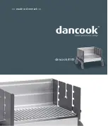
8100
Бренд: dancook Страницы: 16
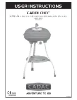
8100
Бренд: Cadac Страницы: 13

CHEF'S Special 4.1
Бренд: FCC BBQ Страницы: 11

HK0521
Бренд: Hark Страницы: 23

PE-800 TBM
Бренд: Pattfield Ergo Tools Страницы: 2

SAFARI CHEF 6547F
Бренд: Cadac Страницы: 14

PA5250
Бренд: SOLAC Страницы: 48

Pro 4s Deluxe
Бренд: Jamie Oliver Страницы: 12

4906807901
Бренд: Scheppach Страницы: 204

VR 230 614
Бренд: Gaggenau Страницы: 32

120SC - 225
Бренд: Quackenbush Страницы: 40

FLORABEST FKG 48 A1
Бренд: Kompernass Страницы: 40

BBC-846 - 2008
Бренд: Fagor Страницы: 46

275685
Бренд: Parkside Страницы: 40

59595071
Бренд: Hausmann Страницы: 25

one CD188D
Бренд: Far Tools Страницы: 35

TE 70-AVR
Бренд: Hilti Страницы: 192

RHGPN11
Бренд: Russell Hobbs Страницы: 20


