ON
I
CON
Flow and Energy Measurement
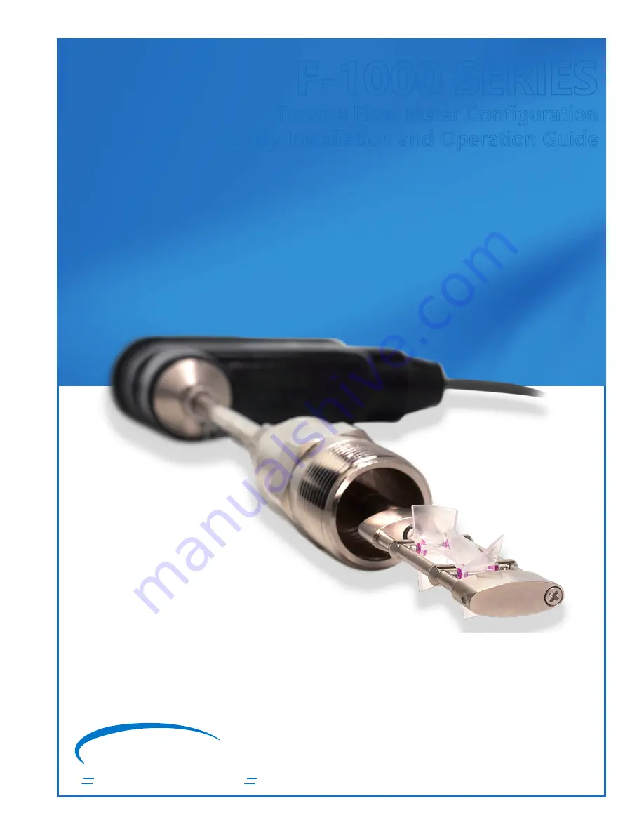
F-1000 SERIES
Turbine Flow Meter Configuration
Utility Installation and Operation Guide
Страница 1: ...ONICON Flow and Energy Measurement F 1000 SERIES Turbine Flow Meter Configuration Utility Installation and Operation Guide ...
Страница 2: ...ver Installation 6 2 2 USB Cable Connection to the Insertion Turbine Meter 8 3 0 HOW TO USE THE CONFIGURATION UTILITY 9 3 1 Opening the Software 9 3 2 Connection Status and Mode Indicators 9 3 2 1 Connection Indicator 9 3 2 2 Status Indicator 10 3 2 3 Mode Indicator 10 3 3 Programming Informational Tabs 11 3 3 1 Meter Data 11 3 3 2 Pipe Selection 13 3 3 3 Flow Settings 17 3 3 4 Frequency Output 19...
Страница 3: ...ONICON s website at https www onicon com products f1000 series turbine flow meters Locate and open the folder which was downloaded Within the folder locate and open the file named TurbineMeter_Configuration_XXX_XXX_XXX exe The XXX_XXX_XXX in the file name will appear as numbers The specific numbers you see are based on the revision of the software provided by ONICON Once this exe file is opened pl...
Страница 4: ...ICON Incorporated 727 447 6140 Page 4 onicon com 3 Complete the user information and click Next 4 Select the installation location and click Next 5 Click Install to proceed with the installation The installation may take a few minutes and once complete a new screen will appear ...
Страница 5: ...THE CONFIGURATION UTILITY If at any point you wish to update the Configuration Utility to a newer version please use the following process 1 Acquire the newest version of the software from ONICON https www onicon com products f1000 series turbine flow meters 2 Uninstall any current versions of the Configuration Utility from your computer Use your computer s Add Remove Programs feature in the Contr...
Страница 6: ... Panel and access the Device Manager Once in the Device Manager open the Other devices tree right click on the Turbine Meter and select Update Driver Software SECTION 2 0 DRIVER INSTALLATION AND USB CABLE 2 1 DRIVER INSTALLATION In the Update Driver Software screen click Browse and select the folder for the Configuration Tool which was provided by ONICON Make sure the Include Subfolder check box i...
Страница 7: ...lation Successful 4 ONICON Smart Turbine Meter is now installed and assigned a COM port number This completes the process to get your computer ready to run the Configuration Utility and interface with the insertion turbine meter Please do not hesitate to contact ONICON Technical Support at 727 447 6140 or email at service onicon com if problems persist with the driver installation ...
Страница 8: ...icro B Male cable to connect to the meter The maximum allowable USB cable length before a powered hub or extender would need to be utilized is 5 meters or 16 feet 5 inches The USB Micro connection is made at the female connector inside the meter s electronics enclosure A Male to Micro B Male USB Cable WARNING The micro USB connection inside the turbine meter enclosure can be easily damaged if the ...
Страница 9: ...ONNECTION STATUS AND MODE INDICATORS Three indicators are available on the top portion of the configurator window Their color and text will change depending on the current operating status of the meter A QR code is also available which will link your cellphone to ONICON s website 3 2 1 CONNECTION INDICATOR This indicator provides information about the current status of the hardware connection to t...
Страница 10: ...ides information about the current status of the alarms and warnings in the Status tab Normal text with green background This status indicates that the meter does not have any warnings or alarms ALARM text with flashing orange background This status indicates that an alarm is present on the meter If you open the Status tab you will find a complete list of the current alarms Warning text with flash...
Страница 11: ...ation about the meter like its serial number manufactured calibrated date meter type and date it was last programmed Meter Data Tab Serial Number Read Only The serial number of the meter is a unique identifier When contacting ONICON for support or additional questions regarding a meter please be ready to provide this serial number If your meter shipped calibrated to a specific pipe size and output...
Страница 12: ...ns the meter type is set at the factory and is read only Relay Output Configuration Editable The relay output can be configured as Not Used Select this option if you do not want to use the scaled or alarm output Scaled Pulsed Output Select this option if you want to configure the relay output as a pulse output for volume totalization Example 1 pulse 10 gallons Alarm Output Select this option if yo...
Страница 13: ...on an accurate pipe ID being programmed in the meter Volumetric Flow Output Average Velocity x Internal Pipe Area Pipe Selection Tab Meter Type Read Only The meter type defines the number of turbines and whether your meter is an insertion inline type F 1100 Single Turbine Insertion Flow Meter F 1200 Dual Turbine Insertion Flow Meter F 1101 and F 1134 Single Turbine Inline Flow Meter The number of ...
Страница 14: ...page IMPORTANT The SET button must be pressed after selecting Table To select a pipe size from the table open the tree to the specific pipe material schedule and size that your meter will be installed in Click on that pipe size and then press the Select Standard Pipe button Once you select the pipe size the ID OD remaining stem lengths and gauge length will auto fill with the correct dimensions Th...
Страница 15: ...Hardware Read Only This length is a calculated value of how much insert able length a meter has left based on the calculated Gauge Length proper insertion depth The remaining stem is a function of the meter length the pipe ID and OD and the type of installation kit The Dry Tap Kit is a ball valve assembly designed to be installed during new construction or when the pipe was drained An example of a...
Страница 16: ...2 FMH for carbon steel pipe The valve assembly height assumed for this calculation is 6 875 IMPORTANT This calculated remaining stem should always be positive If it is negative then that means that the meter cannot reach the proper insertion depth with a valve assembly that is 6 875 or taller If the value is negative the field will be highlighted yellow warning you of this If you have provided you...
Страница 17: ...the flow rate and scaled output units analog output scale and meter damping Flow Setting Tab Full Scale Flow Rate in Volume Rate Units Editable This parameter sets the value for the 20mA 10V 5V analog output full scale if the meter has an analog output The units of measurement will match that set in the Volume Rate Units parameter also on this tab After entering the value on this page press the Se...
Страница 18: ...gpm equivalent of the Full Scale Flow Rate in Volume Rate Units If the units of measurement for both parameters is gpm then they will be identical Volume Rate Units Editable This parameter allows the user to set the units of measurement for the analog output if the meter has one After selecting the desired units press the Set button to permanently program the meter with these flow rate units There...
Страница 19: ... associated with the frequency output on the turbine meter The frequency output is available on every version of the turbine meter The frequency output is typically only used with an ONICON display or BTU meter as a digital input for flow rate and totalization but it can also be used for diagnostics by measuring the speed Hz of the output with a multimeter Full Scale Frequency Output Pulses Per Se...
Страница 20: ...y Factor pulses gallon Read Only This parameter is a calculated value and it provides the scaling factor for measuring the volume rate from the turbine meter s frequency output The units of measurement are pulses per gallon ppg If gpm units were selected in the Flow Settings tab this value will be a duplicate of the previous parameter How to calculate flow rate from the frequency output scale fact...
Страница 21: ...ement for the scaled output This parameter is a duplicate of the parameter with the same name in the Flow Settings tab After selecting the units of measurement press the Set button to accept your changes Scaled Output Multiplier Editable This parameter allows the user to set the volume that each pulse is worth The available selections are 1 10 100 1000 or 10000 units of volume per pulse Press the ...
Страница 22: ... scaled pulse cannot occur more than once per 3 seconds 1 3 Hz The pulse volume along with the pulse duration determine when the meter will enter a pule overrun alarm A pulse overrun occurs when the meter is attempting to provide a scaled pulse faster than the duration allows Please follow the on screen instructions for determining if your pulse scaling and duration settings could cause a pulse ov...
Страница 23: ...m with the turbines The Configurator provides the following options Off The turbine rotation test is disabled Alarm and Run The turbine rotation test will be active in the background If a problem is detected the relay output will close if activated in the Meter Data tab and an alarm will be present in the Status tab The meter will continue to provide a frequency scaled and analog output even thoug...
Страница 24: ... Editable This parameter set the amount of time that the percent difference in turbine rotation must occur before an alarm is triggered The default value is 120 sec This gives the meter a buffer before going into alarm in case debris stopped the turbine momentarily Example with Allowed Percent Difference set at 55 and Turbine Rotation Detect Time Sec set at 120 The Status tab reports that the top ...
Страница 25: ...is parameter reports the average turbine signal pulses per second Hz The average is the mean of the top and bottom turbine signal pulses per second Top Pulses Per Second Read Only This parameter reports the top turbine signal pulses per second Hz If the bottom turbine reports a Hz value yet the top shows none the turbine meter should be inspected for debris or damage Bottom Pulses Per Second Read ...
Страница 26: ...ue shows the flow rate in the user s designated volume unit per minute This is the flow rate of the meter based on the pipe ID programmed in the Pipe Selection tab If the meter is connected directly to a BMS via the analog output or connected to an ONICON display or BTU meter it should be verified that the reading in this parameter matches the BMS ONICON display or BTU meter It should also be conf...
Страница 27: ...of pipe area the turbine meter acquires from being inserted in the pipe to the Gauge Length position Therefore it is equivalent to the Pipe Velocity fps in the Real time Data tab Total Scaled Pulses Read Only This value shows the number of scaled pulses produced by the meter since operation This value is useful for troubleshooting the scaled output on the meter If your BMS is not recording pulses ...
Страница 28: ...per second Hz The average is the mean of the top and bottom turbine signal pulses per second Top Pulses Per Second Read Only This parameter reports the top turbine signal pulses per second Hz If the bottom turbine reports a Hz value yet the top shows none the turbine meter should be inspected for debris or damage Bottom Pulses Per Second Read Only This parameter reports the bottom turbine signal p...
Страница 29: ...value displays the largest average turbine pulse speed Hz measured by the turbine meter at any point during its operation Peak Top Turbine Pulses Read Only This value displays the largest top turbine pulse speed Hz measured by the turbine meter at any point during its operation Peak Bottom Turbine Pulses Read Only This value displays the largest bottom turbine pulse speed Hz measured by the turbin...
Страница 30: ...n this alarm is present the relay output will close if enabled to do so in the Turbine Rotation Test tab Remove the meter and inspect the top turbine for debris if this alarm is present Bottom Turbine Alarm With the turbine rotation test enabled the bottom turbine is rotating at a speed outside the percent difference allowed by the turbine rotation test configuration When this alarm is present the...
Страница 31: ...ioning Not Complete Please contact ONICON if this warning is present Manufacturing Not Complete Please contact ONICON if this warning is present Pulse Overrun This warning occurs when the scaled pulse output for totalization is occurring faster than what is allowed based on the settings in the Scaled Pulse Output tab To resolve this warning either the Scaled Output Multiplier needs to be increased...