


AR0331
28
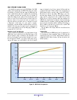
SENSOR FRAME RATE
The time required to read out an image frame (T
FRAME
)
can be derived from the number of clocks required to output
each image and the pixel clock.
The frame-rate is the inverse of the frame period.
fps
+
1
T
FRAME
(eq. 3)
The number of clocks can be simplified further into the
following parameters:
•
The number of clocks required for each sensor row
(line_length_pck)
This parameter also determines the sensor row period
when referenced to the sensor readout clock. (T
ROW
=
line_length_pck x 1/CLK_PIX)
•
The number of row periods per frame
(frame_length_lines)
•
An extra delay between frames used to achieve a
specific output frame period (extra_delay)
T
FRAME
+
1
(CLK_PIX)
[frame_length_lines
line_length_pck
)
extra_delay]
(eq. 4)
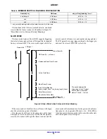
Figure 28. Frame Period Measured in Clocks
Row Period (T
ROW
)
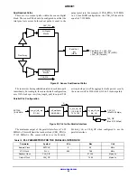
line_length_pck will determine the number of clock
periods per row and the row period (T
ROW
) when combined
with the sensor readout clock. line_length_pck
includes
both the active pixels and the horizontal blanking time per
row. The sensor utilizes two readout paths, as seen in
Figure 21, allowing the sensor to output two pixels during
each pixel clock.
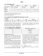
The minimum line_length_pck is defined as the
maximum of the following three equations:
ADC Readout Limitation:
line_length_pck
≥
1100
(eq. 5)
Digital Readout Limitation:
1
3
ƪ
x_addr_end–x_addr_start
)
1
(x_odd_inc
)
1)
0.5
ƫ
(eq. 6)
Output Interface Limitations:
1
2
ƪ
x_addr_end–x_addr_start
)
1
(x_odd_inc
)
1)
0.5
ƫ
)
96
(eq. 7)
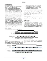
Row Periods Per Frame
frame_length_lines determines the number of row periods
(T
ROW
) per frame. This includes both the active and
blanking rows. The minimum vertical blanking value is
defined by the number of OB rows read per frame, two
embedded data rows, and two blank rows. A minimum
number of idle rows equal to the T2 integration time should
be added in HDR mode to allow for changes in integration
time by an auto exposure algorithm. For example, if the
coarse integration time is 320 lines and the exposure ratio is
16x, then the minimum vertical blanking would be 8 + 2 +
2 + 20 = 32 rows. The minimum (default) number of idle
rows is 4.
Minimum frame_length_lines
+
y_addr_end–y_addr_start
)
1
(y_odd_inc
)
1)
2
)
min_vertical_blanking
(eq. 8)
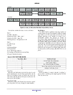
The sensor is configured to output frame information in
two embedded data rows by setting R0x3064[8] to 1
(default). If R0x3064[8] is set to 0, the sensor will instead
output two blank rows. The data configured in the two
embedded rows is defined in “Embedded Data and
Statistics”.