background image

244

SECTION 

8

Se
rial 

Int
e

rf

ac

e (Hos

t Link)

V530-R160

Operation Manual

SECTION 8
Communication with the Host

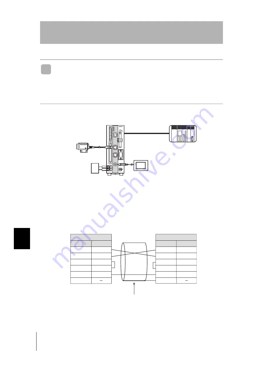
Connection Examples for Programmable Controller 
(Host Link)

This is an example of connection when using a CS1H programmable controller made by
OMRON.

System Configuration

RS-232C Cable Wiring (XW2Z-200T/XW2Z-500T)

The maximum cable length is 15 m. 

VISION MATE

CONTROLLER

V530-R160

POWER

SYNC

Power supply

Camera

Monitor

Programmable Controller

Controller

RS-232C cable

XW2Z-200T (2 m)
XW2Z-500T (5 m)

CPU unit:        CQM1H-CPU**
Power supply: CQM1-PA**
I/O unit:           C200H-ID212

Pin

Controller

Signal

SD

RD

NC

RDB(RD+)

GND

Hood

5

9

Pin

Programmable Controller

Signal

SD

RD

RS

CS

GND

4

5

9

Hood

Only use a shielded cable. 

Содержание V530-R160E

Страница 1: ...2D Code Reader V530 R160E V530 R160EP USER S MANUAL ESC TRIG SHIFT F150 KP CONSOLE ENT Cat No Z169 E1 04...

Страница 2: ...the prior written permission of OMRON No patent liability is assumed with respect to the use of the information contained herein More over because OMRON is constantly striving to improve its high qual...

Страница 3: ...3 SECTION 4 SECTION 5 SECTION 6 SECTION 7 APPLICATION CONSIDERATIONS Precautions for Safe Use Outline Installation and Connections Connection to the Host Basic Operations Setting Reading Conditions Ot...

Страница 4: ...HE BUYER OR USER ALONE HAS DETERMINED THAT THE PRODUCTS WILL SUITABLY MEET THE REQUIREMENTS OF THEIR INTENDED USE OMRON DISCLAIMS ALL OTHER WARRANTIES EXPRESS OR IMPLIED LIMITATIONS OF LIABILITY OMRON...

Страница 5: ...n with the end product machine system or other application or use The following are some examples of applications for which particular attention must be given This is not intended to be an exhaustive...

Страница 6: ...tions for your application on your request Please consult with your OMRON representative at any time to confirm actual specifications of purchased products DIMENSIONS AND WEIGHTS Dimensions and weight...

Страница 7: ...n this manual may result in personal injury or death damage to the product or product failure Please read each section in its entirety and be sure you understand the information provided in the sectio...

Страница 8: ...urposes A lithium battery is built into the V530 R160E EP and may occasionally combust explode or burn if not treated properly Dispose of the Controller as industrial waste and never disassemble apply...

Страница 9: ...power supply cable as short as possible 10 m maximum Use a DC power supply with countermeasures against high voltage spikes safe extra low voltage circuits on the secondary side p 45 Use an appropriat...

Страница 10: ...ine 30 m max Notice for Korea Radio Law Other Precautions Do not attempt to disassemble repair or modify the V530 R160E EP Doing so may cause product failure or a fire If you suspect an error or malfu...

Страница 11: ...ative humidities outside of the 35 to 85 range Presence of corrosive or flammable gases Presence of dust salt or iron particles Direct vibration or shock Direct sunlight Water oil or chemical fumes or...

Страница 12: ...Do not install the V530 R160 in a cabinet containing high voltage equipment Do not install the V530 R160 within 200 mm of power cables Component Installation and Handling OMRON Components Be sure to u...

Страница 13: ...The Memory Card or the V530 R160 itself may be damaged if a Memory Card is removed while power is being supplied Stop the power supply to the Memory Card from the menu Refer to page 172 Turning OFF t...

Страница 14: ...following items are missing V530 R160 2 Dimensional Code Reader Controller Mounting Bracket for rear surface mounting Connector for I O Terminals Qty 1 Phoenix Contact model MC1 5 10 STF 3 5 TRIG A P...

Страница 15: ...SECTION 4 SECTION 5 SECTION 6 SECTION 7 SECTION 8 SECTION 9 SECTION 10 INTRODUCTION Ferrite Core for F150 VM 2D Monitor Cable Qty 1 User s Manual this manual 2D Code Reader V530 R160E V530 R160EP USE...

Страница 16: ...information required to take full advantage of the functions and performance of the product Incorrect application methods may result in the loss of damage or damage to the product Read and follow all...

Страница 17: ...15 V530 R160 Operation Manual INTRODUCTION SECTION 1 SECTION 2 SECTION 3 SECTION 4 SECTION 5 SECTION 6 SECTION 7 SECTION 8 SECTION 9 SECTION 10 INTRODUCTION MEMO...

Страница 18: ...ts 12 Editor s Note 14 Visual Aids 14 Table of Contents 16 Searching from the Menu Tree 22 SECTION 1 Outline 25 What is a 2 dimensional Code Reader 26 Introduction to Functions 28 Operational Flow 32...

Страница 19: ...Lighting 49 Memory Card 51 SECTION 3 Connection to the Host 53 Connecting through the Parallel I O 54 I O Terminal Connections 54 I O Connector Connections 56 Internal Specifications 58 Connecting th...

Страница 20: ...ng 94 Filtering Retry 96 BGS Levels 98 Light Control 100 Setting Reading Conditions DataMatrix 104 Pattern Settings 104 Reading Settings 112 Display Settings 114 Trend Monitor Settings 119 Setting Rea...

Страница 21: ...I O Status with Host Devices I O Monitor 173 Serial Interface 173 Parallel I O Interface 176 SECTION 7 System Settings 179 Entering System Mode 180 Settings Relating to the Camera and Monitor Camera M...

Страница 22: ...CTION 9 Troubleshooting 249 Improving Reading 250 Environment and Setup 250 Conditions Settings 251 Countermeasure Examples 252 Error Codes and Countermeasures 253 Error Messages and Corresponding Cor...

Страница 23: ...onsole 271 F150 KP 2D 271 Camera Cable For F150 S1A 2D Camera 272 F150 VS 2D 272 Monitor Cable 273 F150 VM 2D 273 Parallel I O Cable 274 F160 VP 274 LCD Color Monitor 275 F150 M05L 2D 275 Memory Card...

Страница 24: ...ilt 2 Filt 3 Filt 4 Upper Lower Light control 1 Read DataMatrix Pattern settings Pattern registration Code settings Reference pattern Search region Reading settings Auto pattern select Timeout Number...

Страница 25: ...a Begin read word Write area Begin write word PLC mode check TRIG B mode TRIG C mode TRIG D mode ON state Output period Gate ON delay Gate ON time Multi Drop Output settings Multi Drop Unit number Att...

Страница 26: ...emory card I O monitor Load Serial Save Serial Load Memory card Save Memory card Same as for System data Same as for System data Copy file File operation Drive status Serial Parallel I O Interface Loa...

Страница 27: ...ne 25 V530 R160 Operation Manual SECTION 1 Outline This section introduces the functions and operational flow of the controller What is a 2 dimensional Code Reader 26 Introduction to Functions 28 Oper...

Страница 28: ...a In the case of critical parts that affect safety there were calls for the management of history data for each part Once 2 dimensional code has been printed on a part so that the object and the corre...

Страница 29: ...ader SECTION 1 Outline The Marking can be Done in a Small Space Conventional bar codes were too large to be printed on some smaller parts 2 dimensional codes allow high density information to be packe...

Страница 30: ...reading code within the field of vision Reading cannot be per formed correctly if there are more than one code on a screen Adjust the field of vision of a camera for the 2 dimensional code to be at le...

Страница 31: ...for each process and the reading triggers can be input at TRIG C and TRIG D of the parallel I O Refer to page 194 Sec 8 A memory card slot is provided Memory cards can store settings image and readin...

Страница 32: ...one scene If multiple patterns are registered even codes subject to dispersion in the dot spacing or printing quality can be read It is also possible to read codes with different matrix sizes and symb...

Страница 33: ...n help prevent the occurrence of frequent reading failures and help in the analysis of the cause of reading failures Reading history data can be saved in the memory card Refer to page 119 Sec 5 Image...

Страница 34: ...g the Menu Corresponding to the Code Refer to page 76 Sec 4 step 1 Select the Code and Capture the Image Turn ON the power supply Adjust the Image so it is Easy to Read Refer to page 92 Sec 5 Adjust t...

Страница 35: ...Each Model Refer to page 144 Sec 6 Changing Scenes Scene function Setting Conditions Relating to the System Environment Refer to page 179 Sec 7 System Settings Setting the Communications Specificatio...

Страница 36: ...34 SECTION 1 Operational Flow V530 R160 Operation Manual SECTION 1 Outline MEMO...

Страница 37: ...d Connections This section explains how to install the Controller and connect the peripheral devices Basic System Configuration 36 Component Names and Functions 38 Mounting the Controller 39 Connectin...

Страница 38: ...CAMERA0 MONITOR 24VDC RS 232C 422 POWER TRIG A RESET COMIN RUN ERROR OR BUSY GATE ALARM COMOUT ERROR MEMORY CARD CAMERA1 PARALLEL ESC TRIG SHIFT CONSOLE ENT Controller The V530 R160 reads the 2 dimen...

Страница 39: ...d BNC Jack Attached to F150 VM 2D Monitor cable The Monitor is used to check the image and display menus when making settings Liquid Crystal Monitor Color F150 M05L 2D Pin input F150 SLC20 20 mm field...

Страница 40: ...vibration 12 Covers the compartment that contains the V530 R160 s battery 13 This slot receives the Memory Card 14 Lit when power is being supplied to the Memory Card The Memory Card must not be inser...

Страница 41: ...k Mounting The 2 Dimensional Code Reader can be easily mounted to or removed from 35 mm DIN Track Mounting the Controller Hook the V530 R160 into the DIN Track as shown in the diagram and then press i...

Страница 42: ...ntroller and Mounting Bracket to the mounting sur face with four M4 screws TRIG A POWER RUN ERROR RESET COM IN RUN ERR OR BUSY GATE OR ALARM PARALLEL COMO UT CONSOLE CAMERA 0 MONITOR 24VDC RS 232C 422...

Страница 43: ...and Connections Side Surface mounting Dimensions Unit mm 12 60 0 46 110 66 5 0 46 66 5 0 46 153 7 Four M3 Screw depth 4 8 mm max TRIG A POWER RUN ERROR RESET COM IN RUN ERR OR BUSY GATE OR ALARM PARAL...

Страница 44: ...tion and Connections Bottom Surface mounting TRIG A POWER RUN ERROR RESET COM IN RUN ERR OR BUSY GATE OR ALARM PARALLEL COMOUT CONSOLE CAMERA 0 MONITOR 24VDC RS 232C 422 CAMERA 1 V530 R160 2D CODE REA...

Страница 45: ...the connector leave the cap in place to protect against dust dirt and static electricity Connecting a Console Connect the Console to the V530 R160 s CONSOLE connector An F150 KP 2D Console can be con...

Страница 46: ...terminal screws Use appropriate crimp terminals for M3 screws as shown below Ground Wiring Be sure to wire the protective conductor of the equipment independently To avoid damage to the equipment do n...

Страница 47: ...se a DC power supply with safe extra low voltage circuits on the secondary side If UL recognition is required use a UL class II power supply Cover the power supply with the Terminal Block Protection C...

Страница 48: ...tance must be adjusted each time the lens or Camera is changed because the field of vision and focus vary from lens to lens Also the camera s working distance is an approximate value Mount the camera...

Страница 49: ...for each CCTV lens The values are significantly different for each lens so double check the model of the lens before using the graph The values indicate the lengths of the Extension Tubes The value 0...

Страница 50: ...r Reinforcement may be required for combinations of Extension Tubes exceeding 30 mm if the Camera is subject to vibration 1 32UN 2A 30 dia Max outer dia Total length Lenses and Lens Diameters Lens Foc...

Страница 51: ...a without a light F150 S1A 2D Selecting a Light Does the object have a mirror surface YES NO YES NO YES NO Seen from the front does the code contrast clearly with its background Is there a clear contr...

Страница 52: ...by distinguishing regular and diffuse reflected light Coaxial Lighting Applications Reading codes on transparent objects such as sheet glass Applications Printed markings on paper labels and cardboar...

Страница 53: ...0 s Memory Card slot when the V530 R160 is shipped Remove this filler card and install a Memory Card to use this function If no Memory Card is being used leave the filler card in place to prevent dust...

Страница 54: ...n the card lock 4 Press the eject button over the Memory card slot The memory card will spring out a little 5 Pull the Memory Card straight out from the slot Using Memory Cards in a Personal Computer...

Страница 55: ...V530 R160 Operation Manual SECTION 3 Connection to the Host This section describes how to connect host devices through a parallel I O or serial interface Connecting through the Parallel I O 54 Connect...

Страница 56: ...als to the connector that was included with the V530 R160 and insert the connector into the V530 R160 The following diagram shows the I O alloca tion of the V530 R160 s I O terminals Just wire the ter...

Страница 57: ...lade precision screwdriver to loosen the connec tor s set screw 2 Insert the signal wire 3 Tighten the set screw to secure the wire Tighten to a torque of 0 22 to 0 25 N m 4 Insert the connector into...

Страница 58: ...nnector s mounting screws to secure the connection Turn OFF the power to the V530 R160 before connecting or disconnecting cables Peripheral devices can be damaged if connected or disconnected with the...

Страница 59: ...g B2 DSA Yellow Do not use A3 TRIG B Green Trigger input Continuous level trigger B3 TRIG C Green Trigger input Scene setting level trigger A4 TRIG D Gray Trigger input Scene set ting level trig ger B...

Страница 60: ...kes before turning ON the power supply for the first time Internal Specifications Input Specifications Manufacturer Model Connector Fujitsu FCN 361J040 AU Cover Fujitsu FCN 360C040 B Item Specificatio...

Страница 61: ...ector The following diagram shows the wiring diagram for the STEP signal as an example Item Specification Model V530 R160E NPN mode V530 R160EP PNP mode Output voltage 12 to 24 VDC 10 Load current 45...

Страница 62: ...re Starting Communications Check the following points before starting communications using the serial interface If there is no problem with these settings but proper communications cannot be establish...

Страница 63: ...2 6 The pin alloca tion is shown below RS 422 Block Diagram Use a compatible connector Pin Signal Function FG SD RD NC RDB RD RDA RD SDB SD SDA SD GND Protective frame ground RS 232C RS 232C Not conne...

Страница 64: ...1 1 Connection Personal Computer Cable Wiring XW2Z 200S V XW2Z 500S V The maximum cable length is 15 m Personal computer V530 R160 RS 232C cable V530 R160 XW2Z 200S V 2 m XW2Z 500S V 5 m Pin V530 R160...

Страница 65: ...W2Z 200T XW2Z 500T The maximum cable length is 15 m Programmable Controller V530 R160 RS 232C cable XW2Z 200T 2 m XW2Z 500T 5 m CPU Unit Power Supply Unit or CPU Unit Power Supply Unit V530 R160 CS1H...

Страница 66: ...nk Adapter OMRON NT AL001 recommended OMRON B500 AL001 recommended V530 R160 V530 R160 V530 R160 V530 R160 V530 R160 V530 R160 Notes When using B500 AL001 Please set the terminator to ON and terminate...

Страница 67: ...apter or between Branching Link Adapter Use an AWG22 shielded cable or equivalent For SDB and SDA and RDB and RDA use twisted pair cables Use a shielded cable Pin NT AL001 8 pin terminal block B500 AL...

Страница 68: ...tor Tighten the connector s mounting screws to secure the connection Turn OFF the power to the V530 R160 before connecting or disconnecting cables Peripheral devices can be damaged if connected or di...

Страница 69: ...cribes the basic menu operations Starting the Controller 68 Basic Knowledge of Operations 70 Understanding Setting Operations 76 Select the Code and Capture the Image 76 Set Reading Conditions 79 Perf...

Страница 70: ...ic system components have been connected correctly Refer to page 36 Sec 2 2 Turn ON the power supply on the monitor 3 Turn ON the power supply to the V530 R160 The Camera Monitor setting screen will b...

Страница 71: ...o use Startup Mode when actually operating the V530 R160 Startup Mode is used to set the startup conditions display screen when the V530 R160 is next started For example set the V530 R160 to start in...

Страница 72: ...alue SHIFT Key Must be pressed in combination with another key to have any affect Specific functions are assigned to SHIFT another key for specific screens Up Down Left and Right Keys Up Down Keys Use...

Страница 73: ...ion SET Used to set reading conditions MON Used to confirm the reading can be properly performed under the set condi tions The reading judgements are displayed on the monitor only The results cannot b...

Страница 74: ...input timing will occur before starting to load images This delay is included in the reading time shown in the MON monitor and RUN mode Memory Saved images that were captured previously are displayed...

Страница 75: ...The method for selecting the alternatives is given here The explanation given here uses the Camera Monitor system setting as an example Refer to page 181 Sec 7 1 Move the cursor to the item to be sel...

Страница 76: ...e Time system setting as an example Refer to page 188 Sec 7 1 Move the cursor to the item whose value is to be changed 2 Press the ENT Key The cursor will change to a cursor the size of a single digit...

Страница 77: ...NT Key The character is set and the I cursor moves one space to the right 3 Repeat these steps to input more characters 4 Once all required characters have been input move the cursor to END 5 Press th...

Страница 78: ...eading conditions using Menus and the basic steps before starting readings Select the Code and Capture the Image 1 Move the cursor to MON monitor using the Right Key and press the ENT Key A list of mo...

Страница 79: ...en in 3 will return 5 Press the ESC Key The image read from the camera will be displayed 6 Check that the code of the reading object is displayed on the screen If it is not displayed press the SHIFT D...

Страница 80: ...ct is moving quickly causing the image to blur Refer to page 93 Sec 5 When using a Camera with an Intelligent Lighting Since the lens has a fixed focal point adjust the position of the camera by refer...

Страница 81: ...red for reading There are many other functions apart from these for details see SECTION 5 Setting Reading Conditions Refer to page 91 Sec 5 Entering the SET Mode 1 Move the cursor to MON monitor and p...

Страница 82: ...Shutter Speed 1 Select 0 Image Adjust The Image Adjust selections will be displayed 2 Select Shutter speed The Shutter speed selections will be displayed 3 Select the shutter speed according to the l...

Страница 83: ...White Reverse Refer to page 284 Sec 10 What is Right Left Reverse Refer to page 284 Sec 10 When registering patterns be sure to carry out reading by trigger input and complete teaching for each patte...

Страница 84: ...for the DataMatrix reading will be displayed 2 Select Pattern settings The Pattern list will be displayed 3 Select the pattern number to be registered Up Down Left Right Keys To move among pat tern n...

Страница 85: ...f Finder Pattern setting screen will be dis played 9 Select the first end point of the L shape Draw the L shape by matching it to the shape of the code Up Down Left Right Keys To move the cursor Shift...

Страница 86: ...ENT Key to validate the setting 11 Specify the second end point and the third end point so that they fit the shape of the code 12 Press the ENT Key to validate the setting The selections for the direc...

Страница 87: ...ss the ENT Key Example Selecting 45 when the direction of the code is 0 Set a range of inclination of 45 to 45 Since widening the angle increases the time it takes to read the code set a range that is...

Страница 88: ...teps to register multiple patterns If the result of the teaching is NG go to the screen at 3 pattern list screen delete the pattern adjust the camera focus lighting and so on then carry out pattern re...

Страница 89: ...rformed in the MON monitor mode the test is completed internally by the V530 R160 and the reading judgements are not output to the host 1 Press the ESC Key while the SET mode screen is displayed The M...

Страница 90: ...mode to perform readings Reading judgements can be output to host devices via the serial interface For line operation use this RUN mode 1 Move the cursor to MON monitor and press the ENT Key A list of...

Страница 91: ...ed the existing images will be overwritten in order starting with the oldest Move to SYS Image storing and change the conditions for image storage To store NG images only select Only NG and to store i...

Страница 92: ...he images must be backed up in the computer or the Memory Card if you want to save them long term Refer to page 149 Sec 6 1 The MON monitor mode or RUN mode screen will be displayed 2 Move the cursor...

Страница 93: ...nditions for reading the code This section explains how to adjust the image so that the code is caught clearly by the Camera and the method for setting the Data Matrix and QRCode reading conditions Ad...

Страница 94: ...by the Camera Within the same scene even if the code reading settings Read DataMatrix Read QRCode are changed the settings relating to image input are retained Switching Cameras Two cameras can be co...

Страница 95: ...will be displayed 3 Select Camera 0 or Camera 1 4 Press the ENT Key The setting will be registered and the screen in 2 will return Shutter Speed If the image is unsteady adjust the shutter speed 1 Sel...

Страница 96: ...nitor Select the appropriate filtering while viewing the image The asterisk indicates the default setting Example When Erosion is executed Filtering Target Function OFF Filtering is not performed Smoo...

Страница 97: ...image is manipulated Example Effect of changing the filter size when executing Erosion 1 Select 0 Image Adjust Filtering The Filtering selections will be displayed 2 Select an appropriate filtering me...

Страница 98: ...n this function is set ON the reading processing time is approximately 33 ms longer for one filter 1 Select 0 Image Adjust Filtering retry Selection Description OFF Filtering is not performed Smoothin...

Страница 99: ...en for Filtering retry will be dis played 2 Select the filtering method for Filt 1 3 Press the ENT Key The filtering method will be saved 4 Set the filtering methods for Filt 2 to Filt 4 according to...

Страница 100: ...ot be read densities higher than the set upper limit will be converted to 255 and intermediate densities will be graded between 0 and 255 In other words only the areas with den sities between the set...

Страница 101: ...per value and use the Left and Right Keys to adjust the value Right Key To increase the lowest digit by one SHIFT Right Keys To increase the value 10 times faster Left Key To decrease the lowest digit...

Страница 102: ...ht level 2 is possible The Intelligent Lighting is pulsed in synchronization with the shutter trigger and the light level can be adjusted by changing the width of this pulse If the light level is set...

Страница 103: ...g for each area is shown in a separate digit of the 5 digit number The light level settings range from 0 to 7 a value of 0 is OFF and 7 is the maximum brightness C Sample lighting pattern number There...

Страница 104: ...justing Light Levels by Segment The light level for each area can be set independently between 0 and 7 0 is OFF and 7 is the brightest After selecting one of the sample patterns the light level in eac...

Страница 105: ...etting screen for Light control will be displayed 2 Switch the sample lighting pattern number using the SHIFT Left Right Keys For fine adjustment of light levels move to the desired digit using the Ri...

Страница 106: ...gs for DataMatrix Pattern Settings A finder pattern image is registered in advance then when reading is executed a search is con ducted for an image pattern similar to the input image in order to loca...

Страница 107: ...ry For details on the registration method see SECTION 4 Basic Operations step2 Set Reading Conditions Refer to page 79 Sec 4 Up to 10 patterns can be registered DataMatrix and QRCode cannot be mixed i...

Страница 108: ...nd go to the Pattern registration screen Refer to page 82 Sec 4 Item Description Pattern Selected pattern number Matrix size Matrix size Color Symbol color of the pattern R L rev Execution non executi...

Страница 109: ...e pattern number of the pattern that you want to delete from the Pattern list screen Up Down Left Right Keys To move among pat tern numbers The selected pattern number is indicated with a solid line f...

Страница 110: ...ft reverse is automatically set here OFF ON See note 2 What is Right Left Reverse p 284 Sec 10 Set the range of inclination of the pattern Values that reflect the permissible ranges for code direction...

Страница 111: ...e Pattern list screen Up Down Left Right Keys To move among pat tern numbers The selected pattern number is indicated with a solid line frame 2 Press the ENT Key The Pattern settings selections will b...

Страница 112: ...list screen Up Down Left Right Keys To move among pat tern numbers The selected pattern number is indicated with a solid line frame 2 Press the ENT Key The Pattern settings selections will be display...

Страница 113: ...creen Up Down Left Right Keys To move among pat tern numbers The selected pattern number is indicated with a solid line frame 2 Press the ENT Key The Pattern settings selections will be displayed 3 Se...

Страница 114: ...displayed 3 Make the settings for each item 4 Select Register The setting will be registered and the screen in 2 will return Select whether or not there are to be automatic sub stitutions in the patte...

Страница 115: ...y of use is 0 the controller starts referenc ing from pattern 0 When a registered pattern is deleted the frequency of use of the relevant pattern is cleared Note also that if the controller power is s...

Страница 116: ...ct Display settings Set whether or not guidance is displayed at the bottom of the screen ON OFF Refer to page 116 Specifies whether or not to display reading data on the screen ON OFF Refer to page 11...

Страница 117: ...N 5 Setting Reading Conditions DataMatrix SECTION 5 Setting Reading Conditions The display setting items will be displayed 3 Make the settings for each item 4 Select Register The setting will be regis...

Страница 118: ...ons of the selected items and instructions on subsequent operations Reading Data The read data is displayed If the reading result is NG the error code is displayed Detail Data The settings number of p...

Страница 119: ...on reading Pattern No Displays the registered pattern numbers If the reading result is OK the used pattern number is displayed enclosed in a box If the reading result is NG the used pattern number is...

Страница 120: ...5 Setting Reading Conditions FP Cell Position A cross hair cursor is displayed at the position of the finder pattern FP and positions recognized as cells If a color monitor is used cell recognition p...

Страница 121: ...revent multiple occurrences of defective items and analyze the cause when NG results occur Alarm range level An alarm level is set and an alarm is is sued before NG results occur too fre quently so th...

Страница 122: ...tween the read code and the pattern is displayed This al lows you to detect changes in the status of the code OFF ON Set the alarm range for the correlation value If the cor relation value is less tha...

Страница 123: ...trix The initial screen for the DataMatrix reading will be displayed 2 Select TrendMon settings The Trend Monitor selections will be displayed 3 Select Object of monitoring The setting items will be d...

Страница 124: ...on Red Cont Contrast Green 1 Enter RUN mode to perform readings A graph is displayed Press the SHIFT ENT Keys to clear the history data The measurement values are displayed in a graph Displayed when t...

Страница 125: ...al SECTION 5 Setting Reading Conditions DataMatrix SECTION 5 Setting Reading Conditions RUN mode screen Press the SHIFT Right or Left Keys to switch among the three types of screen 1 Trend Monitor 2 S...

Страница 126: ...a The most recent reading data is displayed 2 Total reads The number of reading executions is displayed 3 OK reads The number of OK reads within the number of executed reads is dis played 4 Read accur...

Страница 127: ...G reading results have occurred and helps analyze the causes of NG results 1 Select TrendMon settings Warning transi tion A graph is displayed 2 Change the displayed NG result using Left Right Keys Le...

Страница 128: ...turned ON a directory designated TRENDMON is automatically created in the root directory of the Memory Card and the data is saved under this directory CSV Format Statistic data The maximum value minim...

Страница 129: ...d 3 Move the cursor to of the file name and press the ENT Key Before the file name is set the date on which the data is saved is input If you do not wish to change the file name proceed to the screen...

Страница 130: ...g Reading Conditions DataMatrix V530 R160 Operation Manual SECTION 5 Setting Reading Conditions The screen in 3 will return 6 Select Execute The data is saved under the TRENDMON directory and the scre...

Страница 131: ...for QRCode Pattern Settings A finder pattern image is registered in advance then when reading is executed a search is con ducted for an image pattern similar to the input image in order to locate the...

Страница 132: ...gger input and complete teaching for each pattern registration You cannot register patterns consecutively without performing teaching processing Up to 10 patterns can be registered for one scene and C...

Страница 133: ...l screen for the QRCode reading will be displayed 2 Select Pattern settings The Pattern list will be displayed 3 Select the pattern number to be registered Up Down Left Right Keys To move among pat te...

Страница 134: ...be displayed 8 Select the desired version What is a version Refer to page 284 Sec 10 The finder pattern range setting screen is dis played 9 Designate the point at the top left of the finder pattern...

Страница 135: ...are at least 5 pixels per cell Refer to pages 46 to 48 Sec 2 What is a pixel Refer to page 283 Sec 10 What is a cell Refer to page 284 Sec 10 10 Designate the bottom left and bottom right points in t...

Страница 136: ...s the ESC Key four times The Monitor mode screen will return 14 Press the TRIG Key to perform teaching If the result of teaching is OK the Symbol color Right Left reverse and Version information are d...

Страница 137: ...attern registration is displayed on the Pattern list screen To register a pattern again or register a new pattern select the pattern number and press ENT Key and repeat the procedure from step 5 Refer...

Страница 138: ...pattern number of the pattern that you want to delete from the Pattern list screen Up Down Left Right Keys To move among pat tern numbers The selected pattern number is indicated with a solid line fra...

Страница 139: ...ere OFF ON See note 2 What is Right Left Reverse p 284 Sec 10 Set the range of inclination of the pattern A value that reflects the permissible range of angle set on pattern reg istration is automatic...

Страница 140: ...Keys To move among pat tern numbers The selected pattern number is indicated with a solid line frame 2 Press the ENT Key The Pattern settings selections will be displayed 3 Select Code settings The s...

Страница 141: ...rn number of the pattern that you want to refer to on the Pattern list screen Up Down Left Right Keys To move among pat tern numbers The selected pattern number is indicated with a solid line frame 2...

Страница 142: ...een Up Down Left Right Keys To move among pat tern numbers The selected pattern number is indicated with a solid line frame 2 Press the ENT Key The Pattern settings selections will be displayed 3 Sele...

Страница 143: ...ottom of the monitor screen is displayed and whether or not reading data is displayed If you increase the number of monitor display items processing time increases proportionately The details of the s...

Страница 144: ...142 SECTION 5 Setting Reading Conditions QRCode V530 R160 Operation Manual SECTION 5 Setting Reading Conditions MEMO...

Страница 145: ...ual SECTION 6 Other Functions This section describes additional functions such as changing scenes or backing up data Changing Scenes Scene Function 144 Backing Up Data 149 Memory Card Operations 163 C...

Страница 146: ...hange to a different reading scene The normal limit of 10 scenes may not be possible for some settings if there is insufficient memory A message will appear on the screen if there is insufficient memo...

Страница 147: ...Scenes Scene Function SECTION 6 Other Functions The Scn 0 to Scn 7 options will be displayed Down Key To display scene numbers 8 to 10 3 Move the cursor to the scene number to be switched to and press...

Страница 148: ...ne data from another scene and changing some settings to suit the new requirements 1 Move the cursor to Scn and press the ENT Key 2 Move the cursor to the desired scene number 3 Press the SHIFT ESC Ke...

Страница 149: ...ing conditions set in scenes This section explains the procedure performed separately for each scene 1 Move the cursor to Scn and press the ENT Key 2 Move the cursor to the number of the scene to be c...

Страница 150: ...when many regions have been registered 1 Move the cursor to Scn and press the ENT Key 2 Move the cursor to the number of the scene for the name change 3 Press the SHIFT ESC Keys The Copy Clear Comment...

Страница 151: ...V530 R160 may not operate properly the next time it is started Data Contents System data Backs up settings under SYS to a personal computer or Memory Card Scene data Backs up settings under SET for e...

Страница 152: ...before turning the power OFF Any new data will be lost if it is not saved to flash memory 1 The MON monitor mode or RUN mode screen will be displayed 2 Move the cursor to MON or RUN and press the ENT...

Страница 153: ...and Windows NT4 0 computers In this example an RS 232C cable is connected to the COM1 port of the computer Alter the example to suit your communications software or COM port number If using different...

Страница 154: ...supported Use the protocol that matches the com puter settings 3 Start the Hyper Terminal program on the computer and make the following communication set tings The same communication settings must be...

Страница 155: ...completed display the MON monitor mode or RUN mode screen 5 Move the cursor to MON or RUN and press the ENT Key The mode selections will be displayed 6 Select TOOL The data selections will be display...

Страница 156: ...e will be displayed 10 Select Execute A screen showing the transfer progress will be dis played 11 Select Transfer Receive File from the computer s Hyper Terminal menu 12 Specify a destination directo...

Страница 157: ...ata 1 Follow the procedure 1 to 3 for Saving Data to connect the V530 R160 and the computer Refer to page 152 2 Select Transfer Receive File from the computer s Hyper Terminal menu 3 Select the file t...

Страница 158: ...Other Functions The data transfer screen will be displayed 6 Once the computer preparations have been completed display the MON monitor mode or RUN mode screen 7 Move the cursor to MON or RUN and pre...

Страница 159: ...will be displayed 10 Select Load Serial 11 If scene data or image data is being trans ferred select the desired scene number or memory number The confirmation message will be displayed 12 Select Execu...

Страница 160: ...up settings data to the Memory Card Turn OFF the power supply to the Memory Card before removing the Memory Card Refer to page 172 Saving Data to a Memory Card V530 R160 to Memory Card 1 Insert the Me...

Страница 161: ...mory card 7 If scene data or image data is being trans ferred select the desired scene number or memory number A list of files in the Memory Card root directory will be displayed C0 indicates the driv...

Страница 162: ...et the file name with up to 8 characters Periods cannot be used in file name 11 Move the cursor to END and press the ENT Key The confirmation message will be displayed 12 Select Execute When saving ha...

Страница 163: ...ving Data to a Memory Card and move to the screen for selecting load destinations Refer to page 158 2 Select Load Memory card 3 If scene data or image data is being trans ferred select the desired sce...

Страница 164: ...n message will be displayed 5 Select Execute When loading has been completed the screen in 1 will return If Image data Load 00 35 Memory card is set the image data in the root directory of the Memory...

Страница 165: ...removed the Memory Card and the V530 R160 may be damaged Refer to page 172 The C0 displayed on the screen while operations are in progress inside the Memory Card indicates the drive name of the Memory...

Страница 166: ...L mode selections will be displayed 5 Select Memory card The Copy file File operation Drive status menu will be displayed 6 Select File operation A list of files in the Memory Card root directory will...

Страница 167: ...sor to END and press the ENT Key The confirmation message will be displayed 11 Select Execute The directory will be created and the screen in 7 will return The directory is displayed in the list of fi...

Страница 168: ...tus menu Refer to page 163 2 Select Copy file A list of files in the Memory Card root directory will be displayed 3 Move the cursor to the file to be copied and press the ENT Key A screen for specifyi...

Страница 169: ...for creating new directories will be dis played Files can be saved in the newly created directory The software keyboard will be displayed 6 Set the file name with up to 8 characters Periods cannot be...

Страница 170: ...checked 1 Follow the procedure 1 to 6 for Creating Directories and display the list of file names Refer to page 163 2 Move the cursor to the file for which the infor mation is to be checked and press...

Страница 171: ...Card can be changed Only the file name can be changed The directory name cannot be changed 1 Follow the procedure 1 to 6 for Creating Directories and display the list of file names Refer to page 163 2...

Страница 172: ...s The software keyboard will be displayed 4 Set the file name with up to 8 characters Periods cannot be used in file name 5 Move the cursor to END and press the ENT Key A confirmation screen will be d...

Страница 173: ...play the list of file names Refer to page 163 2 Move the cursor to the file or directory to be deleted and press the SHIFT ESC Keys A directory can be deleted only when there are no files in that dire...

Страница 174: ...nd free space on the Memory Card will be displayed on this screen 1 Follow the procedure 1 to 5 for Creating Directories and display the Copy file File operation Drive status menu Refer to page 163 2...

Страница 175: ...cations status via serial or parallel I O interfaces Wiring and communications settings can be checked Serial Interface The communications status via the serial interface can be checked 1 The MON moni...

Страница 176: ...screen The screen in 5 will return Display Meaning SO Output to host device Press the TRIG Key once to send a test character string TEST STRING from the V530 R160 to the host device The contents of th...

Страница 177: ...d press the SHIFT ESC Keys The detailed setting screen will be displayed 2 Select ON or OFF for Echo back 3 Move the cursor to the square brackets and press the ENT Key The software keyboard will be d...

Страница 178: ...llel I O Interface The communications status via the parallel I O interface can be checked 1 The MON monitor mode or RUN mode screen will be displayed 2 Move the cursor to MON or RUN and press the ENT...

Страница 179: ...to leave this screen The screen in 5 will return Display Meaning TRIG A Displays the input status for each signal from the host device to the V530 R160 TRIG B TRIG C TRIG D RUN Displays the output st...

Страница 180: ...178 SECTION 6 Checking I O Status with Host Devices I O Monitor V530 R160 Operation Manual SECTION 6 Other Functions MEMO...

Страница 181: ...munications specifications see SECTION 8 Communications with the Host Entering System Mode 180 Settings Relating to the Camera and Monitor Camera Monitor 181 Selecting the Conditions for Image Storage...

Страница 182: ...tion describes how to set conditions related to the system environment It is necessary to enter SYS system mode 1 The MON monitor mode or RUN mode screen will be displayed 2 Move the cursor to MON or...

Страница 183: ...have connected a color monitor select Character color and BG color 5 Select End The setting will be registered and the System mode screen will return Menu item Details Intelligent Lighting 0 Intellig...

Страница 184: ...Go into SYS system mode and select Image storing Refer to page 180 The screen for setting the method of image storage will be displayed 2 Make the settings for each item 3 Select End Menu item Details...

Страница 185: ...mages have been stored new images will be stored by overwriting old images starting with the oldest Even if Only NG is set as the image storage condition the latest read image is saved Reading can be...

Страница 186: ...e and time that the file was created you can determine when a reading NG event occurred By using NG images backed up in the Memory Card for pattern registration you can improve the reading conditions...

Страница 187: ...ltaneously Display capture results When a capture is executed capture in progress will be displayed at the bottom right of the screen After that a directory called IMAGE will automatically be created...

Страница 188: ...reading of objects can be started by simply turning the power ON The asterisk indicates the default setting 1 Go into SYS system mode and select Startup mode Refer to page 180 The Startup mode settin...

Страница 189: ...notifica tion that the host has not accepted a trigger The asterisk indicates the default setting The BUSY signal turns OFF when the reading has been completed 1 Go into SYS system mode and select Err...

Страница 190: ...date and time and adjust if necessary 1 Go into SYS system mode and select Date Time Refer to page 180 The Date Time setting screen will be displayed 2 Check if the date and time is correct Adjust if...

Страница 191: ...e Version Version Use the following procedure to check the model of Controller and the software system version 1 Go into SYS system mode and select Version Refer to page 180 The Version information wi...

Страница 192: ...190 SECTION 7 Checking the Version Version V530 R160 Operation Manual SECTION 7 System Settings MEMO...

Страница 193: ...ons Specifications 192 Trigger Input and Output Formats 194 Timing Charts 195 System Examination 200 Serial Interface Normal 202 Flow Charts 203 Setting Communications Specifications 206 Command List...

Страница 194: ...s This section explains how to set the communications specifications The same communication settings must be used on both the V530 R160 and the host device 1 Move the cursor to RUN or MON and press th...

Страница 195: ...0 TRIG D mode TRIG D Switches to the set scene number and reading is executed with the level trigger specifica tion Scene 0 to 9 default setting Scene 0 ON state Select whether the OK NG signal is tur...

Страница 196: ...ger The currently displayed scene is either continuously read or read until an OK reading judgement TRIG B input invalidates the Reading Settings Number of Retries setting TRIG B changes in the way sh...

Страница 197: ...to signal input at the host Timing Charts One Shot Reading Signal Description OK NG OK OK when 2 dimensional codes are read successfully The reading data is output to the host via the serial interfac...

Страница 198: ...uired for the host device to correctly read the reading judgement Make the output cycle longer than the gate ON delay plus the gate ON time but shorter than the duration of the reading TRIG A input If...

Страница 199: ...be set as required for the host device to correctly read the reading judgement Make the output cycle longer than the gate ON delay plus the gate ON time but shorter than the duration of the reading T...

Страница 200: ...volume and baud rate Note A delay of 33 3 ms max occurs before starting to read images Gate ON delay after the TRIG B signal is turned ON Output signal The function of the signal is the same as for c...

Страница 201: ...dgement OK BUSY OFF ON TRIG B OFF ON Perform reading NG Perform reading OK OK NG RS 232C Note The output time to RS 232C changes depending on the data volume and baud rate Judgement NG Error code BUSY...

Страница 202: ...TRIG A signal is synchronous with the shutter input of the Camera an accurate image of the moving object can be obtained Set the image to be displayed on the monitor to Freeze When through images are...

Страница 203: ...xample Processing time for reading 500 ms Line speed 30 m min The distance moved in 500 ms is 0 25 m Therefore an interval allowing 0 25 m min of move ment is necessary Number of retries If reading is...

Страница 204: ...mable controller are performed in no protocol format via the serial interface Set the SYS Communication RS 232C 422 mode to Normal Refer to page 206 SET mode Command input is not accepted MON mode Com...

Страница 205: ...e CR 140 PRINT READ DATA RESDATA Displaying reading data 150 GOTO 120 Repeat 160 END PC AT computer F160 Controller Output reading data Receive reading data Execute a command Input a command During co...

Страница 206: ...hout outputting it To output the data issue a polling command Note that when the data is output the controller performs the next reading operation and the pre viously read data is overwritten Example...

Страница 207: ...d rate When Xon off is selected for flow control A timeout error occurs if there is no response from the host computer within the set time when Xon off is selected for flow control and it is assumed t...

Страница 208: ...his section explains how to set the communications specifications The same communication settings must be used on both the V530 R160 and the host device 1 Move the cursor to MON or RUN and press the E...

Страница 209: ...be possible to perform communications properly If this happens change the setting to 19200 bps or lower Note 2 The XMODEM 1K protocol is not supported Make the following settings when using the save a...

Страница 210: ...icates the default setting Flow control Communications are carried out while checking the status of the host If there is no response from the host for longer than the set timeout time a timeout error...

Страница 211: ...he communications specifications settings screen The Multi drop setting screen will be displayed 2 Make the settings for each item 3 Select End The setting will be registered and the screen in 1 will...

Страница 212: ...Host Settings for Data Output Set the method for data output to the host 1 Select Output settings on the communica tions specification setting screen The setting screen will be displayed 2 Make the s...

Страница 213: ...e data to be out put The start number is counted from the beginning of the reading data The num ber of digits is not included 1 to 999 default setting 1 End Point When ON is set for Limit Data Functio...

Страница 214: ...lling p 217 RL Outputs reading data to the serial interface Polling with digit position specified p 218 SN Obtains the scene number of the currently displayed scene p 218 Switches to the specified sce...

Страница 215: ...th the Host 1 N connection commands used in multi drop operation Command Function Page GL Performs one reading p 216 RD Outputs reading data to the serial interface Polling p 217 MS Obtains the scene...

Страница 216: ...oxes indicated by num ber 1 Make numerical or other settings if necessary 4 Input the Footer at the end of a command 1 N multi drop connection 1 Specifies the name of the command 2 Insert one space A...

Страница 217: ...s to control the output timing Setting whether or not to add digits 1 1 connection Reading OK Reading NG For error code details refer to Error Codes and Countermeasures on p 253 in Section 9 Trouble s...

Страница 218: ...en the reading is not correctly performed NG reading continues to be per formed for the number of retries specified in the setting conditions See Output Format Refer to page 227 An error will occur if...

Страница 219: ...Function Stops continuous reading RD Function Outputs the latest reading data to the serial interface Polling Command See Output Format Refer to page 227 An error will occur if reading has not been p...

Страница 220: ...ading data will be output The number of digits is not output See Output Formats Refer to page 227 An error will occur if reading has not been performed since the menu items were reg istered SN Functio...

Страница 221: ...ecuted correctly Command not executed correctly DC Function Changes the monitor display status through freeze Set the display code to 0 to specify Through display or 1 to specify Freeze display Comman...

Страница 222: ...cent read processing time Command executed correctly The 5 digit processing time 00000 to 99999 ms is returned if the command was executed correctly A value of 99999 will be returned if the actual pro...

Страница 223: ...of the scene data to the V530 R160 Command executed correctly Command not executed correctly VR Function Reads the system s version information Command executed correctly Example version information...

Страница 224: ...M 1K protocol is not supported The V530 R160 sends the character string READY to the host device when the V530 R160 has completed its initialization Wait for the READY string to be received at the hos...

Страница 225: ...upported The V530 R160 sends the character string READY to the host device when the V530 R160 has completed its initialization Wait for the READY string to be received at the host device before start...

Страница 226: ...ocol is not supported The V530 R160 sends the character string READY to the host device when the V530 R160 has completed its initialization Wait for the READY string to be received at the host device...

Страница 227: ...be output to the host serial interface by simply executing this com mand To output the data send a polling command RD Also no response will be returned if the menu items are not registered RD Function...

Страница 228: ...without a polling command Function 2 Changes the currently displayed scene Set the desired scene number 0 to 9 Data is output from the controller without a polling command Command executed correctly...

Страница 229: ...to use the polling command to control the timing of reading data outputs Select whether or not to include the number of digits of reading data 1 1 connection When the reading is correctly performed Wh...

Страница 230: ...r details on an FCS check program see SECTION 10 Appendix FCS Check Program Exam ple BASIC Refer to page 278 SEC 10 An FCS can only be appended if the communications mode is Normal Refer to page 206 E...

Страница 231: ...ller then the controller outputs the judgement result to the programmable controller System Configuration RS 232C Cable Wiring XW2Z 200T XW2Z 500T The maximum cable length is 15 m VISION MATE CONTROLL...

Страница 232: ...to the operation manual for CQM1H for the ways to change the setting Set the read command Set DM0100 to 4047 and DM0100 to 4C00 Settings at the Controller Make the following communication settings It...

Страница 233: ...DM220 RXD 47 DM200 0000 AR9 END 01 AR8 06 000005 Programming to receive read data Programming to send read command Sample ladder program END The end of the program AR8 06 RS 232C port reception comple...

Страница 234: ...1 1 connection can be used with the host link mode 1 N connections are not supported SET mode Command input is not accepted MON mode Command input is accepted but reading results are not output to th...

Страница 235: ...number 00 Fixed F160 Controller Returns a command Clears the contents of the Read Area to zero Issues a 0 clear command Returns write completed response Command requires output of reading data Writes...

Страница 236: ...r will occur if the next input occurs before communications have been com pleted While the command is being executed the BUSY signal of the parallel I O interface is ON TRIG A A timeout error occurs i...

Страница 237: ...signal of the parallel I O interface is ON A timeout error occurs if there is no response within 5 seconds and it is assumed that the line is broken or the programmable controller is not working corr...

Страница 238: ...Communication Mode The methods for setting the communication speed and data length are explained here The same communication settings must be used on both the V530 R160 and the host device 1 Move the...

Страница 239: ...andard depending on the cable length if 38400 bps or a higher setting is selected it may not be possible to perform communications properly If this happens change the setting to 19200 bps or lower Not...

Страница 240: ...llers Set the Read Area where the controller checks the command and the Write Area where the reading result is output 1 Select Host link on the communications specifications setting screen The Host li...

Страница 241: ...default setting 0 Write area Select the relay where the controller outputs execution results I O HR holding relay LR link relay DM data memory None No writing Begin write word Set the first word to w...

Страница 242: ...n the Read Area Command list Command code Function Page 0010 Performs one reading p 241 0011 Starts continuous reading p 241 0012 Stops continuous reading p 241 0020 Switches to the specified scene nu...

Страница 243: ...e reading is not correctly performed NG reading continues to be per formed for the number of retries specified in the setting conditions The reading result is output to the Write Area Refer to page 24...

Страница 244: ...When the current scene number is 0 the scene number will switch to 9 0023 Obtain displayed scene number Function Obtains the scene number of the currently displayed scene Write flag switches between 0...

Страница 245: ...the reading data consists of an odd number of bytes a space ASCII code 20 is inserted For error code details refer to Error Messages and Corresponding Corrective Actions in Section 9 Troubleshooting R...

Страница 246: ...System Configuration RS 232C Cable Wiring XW2Z 200T XW2Z 500T The maximum cable length is 15 m VISION MATE CONTROLLER V530 R160 POWER SYNC Power supply Camera Monitor Programmable Controller Controlle...

Страница 247: ...make the settings refer to the manual for the programmable controller Settings at the Controller Item Setting Communication method Host link Unit number 00 Baud rate 9600 bps Data length 7 bit Parity...

Страница 248: ...to the spec ified words in the Programmable Controller 1 Set the reading conditions of the V530 R160 and set the reading mode to RUN mode 2 Set the Start Reading Command in DM0100 of the Programmable...

Страница 249: ...bit unit output settings are not possible Settings at the controller MOV 021 0010 D0100 W0 00 DIFU 013 W0 00 I 2 00 MOV 021 0021 D0100 W0 01 DIFU 013 W0 01 I 2 01 MOV 021 0022 D0100 W0 02 DIFU 013 W0...

Страница 250: ...248 SECTION 8 Serial Interface Host Link V530 R160 Operation Manual SECTION 8 Communication with the Host MEMO...

Страница 251: ...Troubleshooting This section explains the countermeasures to take when reading cannot be executed correctly or when trouble occurs Improving Reading 250 Error Codes and Countermeasures 253 Error Mess...

Страница 252: ...of it can be read resulting in an NG reading because of hollowing of dots increase the field of vision The effects of hollowing can be prevented If the cell recognition coordinates are incorrect decr...

Страница 253: ...en detected Has cell recognition been performed properly If ON is set for Display settings FP Cell position the finder pattern and cell recog nition position can be checked on the monitor Refer to pag...

Страница 254: ...luence of dots can be reduced by activating the Dilate or Erosion function of 0 Image Adjust Filtering The influence of dots can be further reduced using the smoothing function 0 Image Adjust Filterin...

Страница 255: ...rns in the X or Y directions may be stained or damaged Check the condition of the timing pattern Check the matrix size setting The size may not be set correctly Register the pattern again The register...

Страница 256: ...E200 Timeout Error Decoding was not performed within the time out time Make the reading angle in Pattern set tings Code settings smaller Lengthen the Reading settings Timeout Change the angle of visio...

Страница 257: ...set tings FP Cell position is turned ON Register the pattern again The registered pattern may not be the opti mum one p 114 E005 Finder Pattern Over Multiple finder patterns have been detected Increas...

Страница 258: ...be incorrect p 256 E020 Decode Error No definition error The printing is in a special format and not defined for the V530 R160 e g link mode Change the printing format E200 Timeout Error Decoding was...

Страница 259: ...ed p 181 Camera connection is incorrect Are the Camera Cables connected to the V530 R160 Is the Camera Cable disconnected from the Cam era Check the setting for SYS Camera Monitor then turn the power...

Страница 260: ...properly Reason Data transfer has been interrupted due to a commu nications error in communications between the V530 R160 and a host device If the same error message appears after restart it may mean...

Страница 261: ...the directory name The following characters cannot be used Same directory name has already existed Specify a directory name that is not being used Same file name has already existed Specify a file na...

Страница 262: ...eate free space Replace the Memory Card with a bigger capacity card Insufficient flash memory Delete unnecessary scenes Insufficient model memory Reduce the size of the registered patterns Delete unne...

Страница 263: ...from the power sup ply or cables The Monitor Cable is not connected properly Cannot make key inputs on the Con sole The Console Cable is not correctly connected p 43 Camera images are not displayed wh...

Страница 264: ...The signal line is disconnected The cables are not correctly wired The V530 R160 is not in RUN mode p 87 p 176 p 56 Symptoms Causes and remedies No communications are possible The cables are not corre...

Страница 265: ...ON 10 Appendix Maintenance 264 Maintaining and Changing a Camera with a Light 264 Replacing the Battery 266 Regular Inspections 267 Specifications and Dimensions 268 ASCII Codes 277 FCS Check Program...

Страница 266: ...Camera 2 Remove the light cable from the slot in the camera base 3 Remove the two screws that secure the Light 4 Remove the bottom two screws that secure the Light 5 Remove the Light from the Camera 6...

Страница 267: ...ing the Light 1 Fit the light in the Camera 2 Replace the bottom two screws that secure the Light 3 Replace the two screws that secure the Light 4 Insert the light cable in the slot in the camera base...

Страница 268: ...screwdriver The battery is mounted to the inside of the battery cover 2 Hold the battery connector by its base and pull it off 3 Cut the binding band that secures the battery and remove the battery f...

Страница 269: ...e voltage measured at the power supply terminals on the terminal block must be 20 4 VDC to 26 4 VDC Circuit tester Ambient temperature The operating ambient temperature inside the cabinet must be betw...

Страница 270: ...ween all DC external terminals and GR termi nal with internal surge absorber removed Leakage current 10 mA max Noise resistance 2000 V rise time 5 ns pulse width 50 ns Burst continuation time 15 ms Pe...

Страница 271: ...0 5 1 5 31 30 7 21 7 Unit mm 20 0 1 21 25 2 31 25 2 6 2 6 2 29 11 15 5 14 5 16 75 6 75 Two M4 holes with depth of 8 1 4 20UNC with depth of 8 1 32UN 2A C mount Camera Cable Connector 11 8 dia Light Co...

Страница 272: ...t0 6 SECC C Case Die cast aluminium alloy ADC 12 Mounting base Bakelite containing cloth back Light materials Case ABS Transparent aperture PC Performance Specifications Camera Characteristics Pictur...

Страница 273: ...amplitude 0 15 mm 4 times for 8 minutes each in 3 directions Shock resistance 196 m s2 3 times each in 6 directions Ambient temperature Operating 0 to 50 C Storage 25 to 65 C with no icing or condensa...

Страница 274: ...25 to 65 C with no icing or condensation Ambient humidity Operating storage 35 to 85 with no condensation Ambient environment No corrosive gasses Materials Cable sheathing Heat resistant vinyl chlorid...

Страница 275: ...de 0 15 mm 4 times for 8 minutes each in 3 directions Shock resistance 196 m s2 3 times each in 6 directions Ambient temperature Operating 0 to 50 C Storage 25 to 65 C with no icing or condensation Am...

Страница 276: ...Hz half amplitude 0 15 mm 4 times for 8 minutes each in 3 directions Shock resistance 196 m s2 3 times each in 6 directions Ambient temperature Operating 0 to 50 C Storage 25 to 65 C with no icing or...

Страница 277: ...n 3 directions Shock resistance 150 m s2 3 times each in 6 directions Ambient temperature Operating 0 to 50 C Storage 25 to 65 C with no icing or condensation Ambient humidity Operating storage 35 to...

Страница 278: ...N128S Unit mm 3 3 42 8 36 4 General Specifications Ambient temperature Operating 0 to 60 C Storage 25 to 85 C with no icing or condensation Ambient humidity Operating storage 8 to 95 with no condensa...

Страница 279: ...0 SECTION 10 Appendix ASCII Codes Data read with Normal commands of the serial interface is output in two characters of ASCII code The ASCII codes correspond to the following characters Example When t...

Страница 280: ...utine Examples for Received Data 1000 FCSHECK 1010 FCSHECK 1020 Q 0 FCSCK OK 1030 PRINT RESPONSE 1040 LENGS LEN RESPONSE 3 1050 FCSP MID RESPONSE LENGS 1 2 1060 FOR J 1 TO LENGS 1070 Q ASC MID RESPONS...

Страница 281: ...taMatrix ECC200 In the diagram below the matrix size is 12 12 What is Maximum Data Capacity Refer to page 284 Matrix size Data Capacity Numerals Alphanu meric charac ters Alphanumer ics and sym bols K...

Страница 282: ...efer to page 284 15 cells 15 cells Matrix size Data Capacity Numerals Alphanu meric charac ters KANA 1 byte 9 9 3 2 1 11 11 12 8 5 13 13 24 16 10 15 15 37 25 16 17 17 53 35 23 19 19 72 48 31 21 21 92...

Страница 283: ...3 4 3 2 15 15 13 9 6 17 17 24 16 10 19 19 36 24 16 21 21 50 33 22 23 23 65 43 28 25 25 82 54 36 Matrix size Data Capacity Numerals Alphanu meric charac ters KANA 1 byte 13 13 1 1 15 15 8 5 3 17 17 16...

Страница 284: ...rsion 1 L 7 41 25 17 10 M 15 34 20 14 8 Q 25 27 16 11 7 H 30 17 10 7 4 25 25 Version 2 L 7 77 47 32 20 M 15 63 38 26 16 Q 25 48 29 20 12 H 30 34 20 14 8 29 29 Version 3 L 7 127 77 53 32 M 15 101 61 42...

Страница 285: ...was developed in Japan High speed reading is possible with QRCodes but the code size is quite large compared to other 2 dimensional codes Error correction This term is used to describe the function w...

Страница 286: ...ht direction Black and white rever sal Usually in images of 2 dimensional codes the code itself is black and the back ground is white Sometimes however due to the material of the reading object and th...

Страница 287: ...60 can display images via a monitor using approximately 250 000 pixels 512 484 This means that if the field of vision is 512 mm 484 mm the resolu tion will be 1 mm pixel Marking methods There are seve...

Страница 288: ...286 SECTION 10 Glossary SECTION 10 V530 R160 Operation Manual SECTION 10 Appendix MEMO...

Страница 289: ...ameras 10 Cameras and Cables 10 Cameras Lenses Lighting and Memory Cards 46 CCTV Lenses 47 Changing File Names 169 Changing Options 73 Changing Scenes Scene Function 144 Changing Test Character String...

Страница 290: ...t 241 FP Cell Position 118 G General Safety Precautions 24 Glossary 283 Ground Wiring 44 Guidance 116 I I O Connector Connections 56 I O Format 214 240 I O Terminal Connections 54 Image data can be ba...

Страница 291: ...Reference Pattern 110 139 Referring to NG Reading Results Warning Transition 125 Registering Models of Finder Pattern 81 Regular Inspections 267 Regulations and Standards 10 Removing the Controller 39...

Страница 292: ...tion 200 T Tact time 201 The Marking can be Done in a Small Space 27 The reading results over time can be ex pressed in the form of a graph 31 Timing Charts 195 To delete a pattern 107 136 Touching Si...

Страница 293: ...ion changed Page 6 Precaution added 03 May 2006 Pages 11 and 272 Description on Video Monitor deleted Pages 36 and 45 Power Supply model number changed Page 36 Monitor cable connector changed Page 36...

Страница 294: ...60169 U S A Tel 1 847 843 7900 Fax 1 847 843 7787 Regional Headquarters OMRON EUROPE B V Wegalaan 67 69 2132 JD Hoofddorp The Netherlands Tel 31 2356 81 300 Fax 31 2356 81 388 Contact www ia omron com...

Отзывы: