background image

5-2

Install Options

This section describes the installable options for the IPC Machine Controller.

5-2-1

Install a Drive

A drive is a storage device for the IPC Machine Controller.

Additional Information

• Depending on the product configuration a drive is already installed.

Refer to 

1-4 Product Configuration

 on page 1 - 6 for storage details.

• Depending on the CPU type one or two drives are supported.

Refer to 

4-1-4 CPU Specifications

 on page 4 - 5 for the number of supported drives.

• Refer to 

3-9-3 Storage Devices

 on page 3 - 23 for the recommended drive models.

• Refer to 

4-1-6 Storage Device Specifications

 on page 4 - 6 for drive specifications.

Prepare the following items:
• The drive

A drive is not supplied with the Panel PC.

• The drive bracket with mounting screws

These are supplied with the Panel PC.

To install a drive:

1

Ensure the Panel PC is OFF.

2

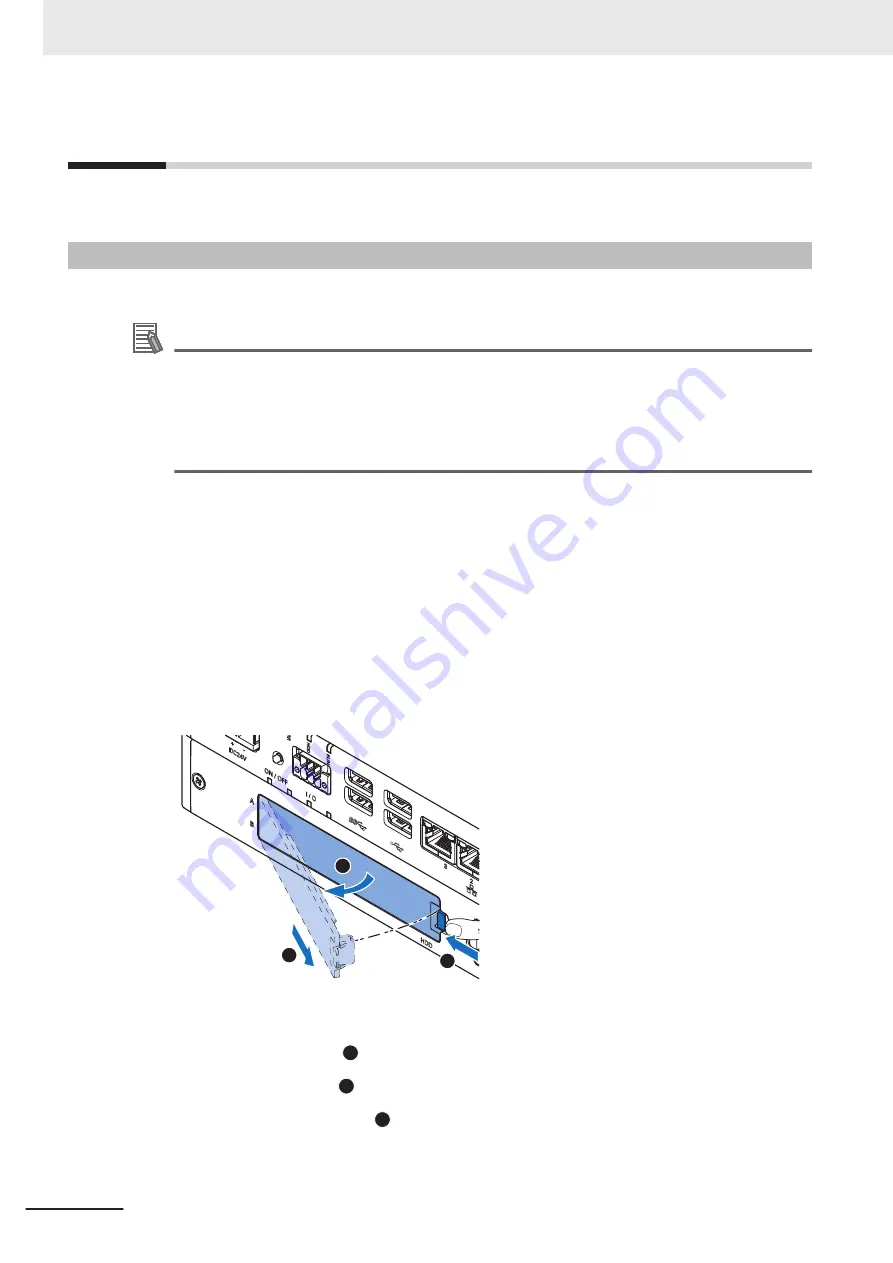
Remove the drive cover.

1

3

2

(1) Push the lock lever 

1

.

(2) Tilt the drive cover 

2

.

(3) Remove the drive cover 

3

.

5 Installation

5 - 4

NY-series Industrial Panel PC Hardware User's Manual (W557)

Содержание NY532-1*00-111*13**0

Страница 1: ...Industrial PC Platform NY series IPC Machine Controller Hardware User s Manual NY532 1 00 111 13 0 NY532 1 00 112 13 0 Industrial Panel PC W557 E2 04 Industrial Panel PC...

Страница 2: ...ined in this publica tion Trademarks Sysmac and SYSMAC are trademarks or registered trademarks of OMRON Corporation in Japan and other countries for OMRON factory automation products Windows Visual Ba...

Страница 3: ...st also have knowledge of electrical sys tems an electrical engineer or the equivalent Personnel in charge of introducing Factory Automation systems Personnel in charge of designing Factory Automation...

Страница 4: ...eries Instructions Reference Manual NY series IPC Machine Controller Industrial Panel PC Industrial Box PC Motion Control User s Manual NY series Motion Control Instructions Reference Manual NY series...

Страница 5: ...in EtherCAT Port User s Manual NY series IPC Machine Controller Industrial Panel PC Industrial Box PC Built in EtherNet IP Port User s Manual NY series Troubleshooting Manul Writing the user program...

Страница 6: ...peration 19 Operation 20 General Communications 21 EtherNet IP Communications 21 EtherCAT Communications 21 Motion Control 22 Restoring Data 23 Battery Replacement 23 Product Replacement 23 Cleaning M...

Страница 7: ...urations 2 2 2 2 EtherCAT Network Configuration 2 3 2 2 1 Related EtherCAT Hardware 2 4 2 3 EtherNet IP Network Configuration 2 5 2 3 1 Related EtherNet IP Hardware 2 5 2 4 Connection with the Sysmac...

Страница 8: ...wer Consumption Specifications 4 4 4 1 4 CPU Specifications 4 5 4 1 5 Memory Specifications 4 5 4 1 6 Storage Device Specifications 4 6 4 1 7 PCIe Card Specifications 4 7 4 2 Connector Specifications...

Страница 9: ...ON 6 3 6 2 1 Power ON Using the Power Button 6 3 6 2 2 Power ON Using the Power ON OFF Input 6 3 6 2 3 Power ON Using Safe Mode 6 4 6 2 4 Auto Power ON 6 4 6 3 Power OFF 6 5 6 3 1 Power OFF Using the...

Страница 10: ...urity A 10 A 1 7 BIOS Save Exit A 10 A 2 Allocate a Drive in Windows A 11 A 3 DVI Connector Pin Details A 12 A 3 1 DVI I Connector Pin Details A 12 A 3 2 DVI D Connector Pin Details A 13 A 4 RS 232C C...

Страница 11: ...of the package and save them Inform your supplier immediately 2 Open the package Ensure not to damage the contents 3 Ensure that all items are present Additional Information Refer to 5 1 2 Items Supp...

Страница 12: ...utions on what to do and what not to do to ensure proper operation and performance Additional Information Additional information to read as required This information is provided to increase understand...

Страница 13: ...ed that in no event shall Omron be re sponsible for warranty repair indemnity or any other claims or expenses regarding the Products un less Omron s analysis confirms that the Products were properly h...

Страница 14: ...all not be responsible for the user s programming of a programmable Product or any consequence thereof Omron Companies shall not be responsible for the operation of the user accessible operating sys t...

Страница 15: ...Companies has been checked and is believed to be accurate how ever no responsibility is assumed for clerical typographical or proofreading errors or omissions Terms and Conditions Agreement 13 NY ser...

Страница 16: ...perty damage Symbols The circle and slash symbol indicates operations that you must not do The specific operation is shown in the circle and explained in text This example indicates prohibiting disass...

Страница 17: ...ut Units in the following cas es The slaves will operate according to the settings in the slaves If an error occurs in the power supply If a CPU watchdog timer error or CPU reset occurs If a major fau...

Страница 18: ...e touchscreen in applications that involve human life in applications that may result in serious injury or for emergency stop switches Downloading Always confirm safety at the destination before you t...

Страница 19: ...uct Non isolated Device Non isolated Interface 24 VDC 0 VDC Never ground the 24 VDC side of the power supply This may cause a short circuit Online Editing Execute online editing only after confirming...

Страница 20: ...r other foreign material to enter any product Otherwise the product burning failure or malfunction may occur Cover the product or take other suitable countermeasures especially during wiring work Wiri...

Страница 21: ...t and an external monitor Always check the power supply and power connections before applying power Incorrect power con nections can damage the product or cause burning Always turn OFF the power suppl...

Страница 22: ...f personal injury due to hot or rotating parts Press the power button for several seconds to force the product shutdown Always back up files in the planned way to prevent data loss or system file corr...

Страница 23: ...ngs use the Sysmac Studio to check the slave revision settings in the master and the actual slave revisions and then make sure that functionality is compatible in the slave manuals or other references...

Страница 24: ...nals are longer than the control period of the MC Function Module If the input signal widths are shorter than the control period the MC Function Module may not be able to detect the input signals resu...

Страница 25: ...ed to excessive shock Batteries that have been subjected to shock may leak if they are used UL standards require that only an experienced engineer replace the Battery Make sure that an ex perienced en...

Страница 26: ...erchlorate Material special handling may apply See http www dtsc ca gov hazardouswaste perchlorate The product contains a lithium battery with a perchlorate content of 6ppb or higher When exporting an...

Страница 27: ...uch a grounded piece of metal to discharge static electricity from your body before starting an installation or maintenance procedure Insert USB devices and PCIe devices correctly to avoid the burning...

Страница 28: ...de is also required to use those func tions Refer to Version Information for NY series Controllers for the relationship between the unit versions of the controller and the Sysmac Studio versions and f...

Страница 29: ...n Module may access slave with a different node address than the specified node address or the error may not be reset correctly Make sure that the communications distance number of devices connected a...

Страница 30: ...sure it is in place Cleaning and Maintenance Do not use corrosive substances to clean the product Turn OFF the product or disable the touchscreen for cleaning with water Precautions for Correct Use 28...

Страница 31: ...e occurs the user may be required to take appropriate meas ures Applicable Directive EMC Directive EMC Directive OMRON devices that comply with EU Directives also conform to the related EMC standards...

Страница 32: ...roduct that complies with UL or CSA standards and must apply those standards to your machinery or devices refer to this manual This manual provides the application conditions for complying with the st...

Страница 33: ...3 ID Information Label on page 1 5 for label details Check Unit Versions with the Sysmac Studio You can use the Sysmac Studio to check unit versions Additional Information Refer to the NY series IPC...

Страница 34: ...are revisions Additional Information Refer to the NY series IPC Machine Controller Industrial Panel PC Industrial Box PC Software User s Manual Cat No W558 for the Sysmac Studio procedures to determin...

Страница 35: ...l Box PC Hardware User s Man ual W556 NY512 1 Learning all basic infor mation about the Indus trial Box PC with Ma chine Automation Con trol Software This in cludes introductory in formation installat...

Страница 36: ...Instruc tions Reference Manual W561 NY532 NY512 1 Learning the specifica tions of the motion con trol instructions of an NY series Industrial PC with Machine Automa tion Control Software The motion co...

Страница 37: ...Con nection Check and Start Op eration Maintenance and In spection Shutdown Process ing I O Signal Functions Troubleshooting Industrial Monitor Manual This table contains the related manual of the Ind...

Страница 38: ...within a computer that executes the in structions of a computer program DVI Digital Visual Interface DVI D A Digital Visual Interface with only Digital signals DVI I A Digital Visual Interface with A...

Страница 39: ...runtime a mo tion control engine and potentially a robotics engine MSDN Microsoft Developer Network Merge module A module providing a standard method by which developers deliver shared Win dows instal...

Страница 40: ...preventive maintenance actions Added NY Monitor Link option Modified UPS configuration procedure Minor modifications 03 April 2017 Made changes accompanying release of unit version 1 14 of the Contro...

Страница 41: ...ecifications Installation Hardware Overview System Configurations Introduction to the Industrial Panel PC 1 2 3 4 5 6 1 2 3 4 6 5 1 7 7 Appendices Maintenance A A Sections in this Manual 39 NY series...

Страница 42: ...Sections in this Manual 40 NY series Industrial Panel PC Hardware User s Manual W557...

Страница 43: ...IPC Machine Controller 1 1 Intended Use 1 2 1 2 Features 1 3 1 2 1 Hardware Features 1 3 1 2 2 Machine Controller Software Features 1 4 1 3 ID Information Label 1 5 1 4 Product Configuration 1 6 1 5...

Страница 44: ...sily integrated in manufacturing innovations like big data NUI and IIoT with out compromising on the proven reliability and robustness of a PLC The IPC Machine Controller has a compact design that off...

Страница 45: ...d with unified communications specifications and user interface specifications The IPC Machine Controller are part of the Sysmac Series You can use them together with EtherCAT slaves other Sysmac prod...

Страница 46: ...lt in I O for UPS status and Panel PC shutdown control are provided 4 USB ports 2 USB2 0 ports and 2 USB3 0 ports are provided for connection to external USB devices such as keyboards memory sticks or...

Страница 47: ...ontroller Software G LOT number and serial number Production details consisting of The lot number of the IPC Machine Controller in the format DDMYY DDMYY with Month number 1 to 9 for January to Septem...

Страница 48: ...on module 1 Standard 6 Number of axes for motion con trol 3 16 axes 4 32 axes 5 64 axes 7 Additional Function Software Module 0 8 Reserved 0 9 Expansion slots 1 1 PCIe slot 10 Frame type 1 Aluminum fr...

Страница 49: ...ep 2 Setup the Machine Controller Software Create the system configurations that you designed in step 1 1 and 1 2 and assign the variables Create the tasks and programs and debug them e g with simulat...

Страница 50: ...ware User s Manual Cat No W558 Sysmac Studio Version 1 Operation Manual Cat No W504 Step 6 Check and then Start Actual Operation Configure Windows install applications and download the machine control...

Страница 51: ...work Configuration 2 3 2 2 1 Related EtherCAT Hardware 2 4 2 3 EtherNet IP Network Configuration 2 5 2 3 1 Related EtherNet IP Hardware 2 5 2 4 Connection with the Sysmac Studio 2 7 2 4 1 Configuratio...

Страница 52: ...connect an Omron Industrial Monitor using a single cable 2 bays for HDD and or SSD storage devices 1 SD Memory Card slot for removable storage 1 PCIe Card Slot to add support for other industrial net...

Страница 53: ...nd Inverters I O controls Safety devices NY series IPC Machine Controller Sysmac Studio Automation Software EtherNet IP Port 2 Port 3 Additional Information Refer to the NY series IPC Machine Controll...

Страница 54: ...17 for port specifications EtherCAT Slaves A device that exchanges data with the EtherCAT master built into Machine Controller Software through the EtherCAT network The device provides non synced Eth...

Страница 55: ...therNet IP Hardware IPC Machine Controller The Machine Controller Software located on the Panel PC is the central controller for machine auto mation Ethernet port 2 on the Panel PC is the built in Eth...

Страница 56: ...to the EtherNet IP system Additional Information Refer to the NY series IPC Machine Controller Industrial Panel PC Industrial Box PC Built in EtherNet IP Port User s Manual Cat No W563 for details 2 S...

Страница 57: ...ection device You can make the connection either with or without an Ethernet switch You can use either a cross cable or a straight cable Specify the IP address of the remote node from the Sysmac Studi...

Страница 58: ...provide a connection to the Sysmac Stu dio Routing through CS CJ series EtherNet IP Units Ports You cannot connect to an NY series Panel PC by routing through a CS CJ series Ethernet IP Unit or port...

Страница 59: ...I O Connector 3 15 3 7 3 USB Connectors 3 16 3 7 4 Ethernet Connectors 3 17 3 7 5 DVI Connector 3 17 3 7 6 RS 232C Connector Optional 3 18 3 7 7 DVI D Connector Optional 3 18 3 7 8 NY Monitor Link Con...

Страница 60: ...B D A C Item Name Description A Logo LED Backlit logo with adjustable brightness B Status LED indicator LED to indicate power and connection status with adjustable brightness C ID information label L...

Страница 61: ...active cooling The battery replacement date The license key for the operating system optional B Ground terminal Provides a ground terminal for the Panel PC C Option port Interface connection options...

Страница 62: ...of the connectors Drive bay B Bay for an optional drive 2 for additional storage Drive bay B is the bay at the side of the display L I O connector 2 inputs Power ON OFF Input and UPS Mode Input and 1...

Страница 63: ...ports 1 for the Machine Controller Software These connectors do not give access to the Windows Operating System 1 Refer to 4 2 4 Ethernet Connector Specifications on page 4 14 for Ethernet specificati...

Страница 64: ...lable A B C D Item LED Indicator Name Description A PWR Power Indicates the operating mode of the Panel PC B ERR Error Indicates the presence and type of an error C HDD Hard Disk Drive Indicates HDD S...

Страница 65: ...olor Status Meaning Yellow Flickering The HDD or SSD is active RUN LED Indicator The RUN LED indicates the status of the Machine Controller Software Color Status Meaning Green Not lit Machine Controll...

Страница 66: ...he Power and Error LEDs on the bottom of the IPC Machine Controller The following LEDs are available on the front of the IPC Machine Controller B A Item LED Description A Logo LED LED to backlight the...

Страница 67: ...itor Utility information is available For products NYM in the section Software in this manual For products NYP in the section Support Software in this manual For products NY5 in the NY series IPC Mach...

Страница 68: ...r Power supply defective Monitor internal hardware error At controllable brightness in following situations Thermal shutdown Watchdog Error Additional Information Refer to Industrial Monitor Utility i...

Страница 69: ...witch the Panel PC ON and OFF Additional Information Refer to 6 2 Power ON on page 6 3 for ON details Refer to 6 3 Power OFF on page 6 5 for OFF details 3 Hardware Overview 3 11 NY series Industrial P...

Страница 70: ...on Refer to 4 1 4 CPU Specifications on page 4 5 for the number of supported drives Refer to 4 1 6 Storage Device Specifications on page 4 6 for storage device specifica tions Refer to 5 2 1 Install a...

Страница 71: ...Cards with the following specifications SDHC type SD 2 0 specification Up to 32 GB capacity Additional Information Refer to 3 9 1 SD Memory Cards on page 3 22 for SD Memory Card details 3 Hardware Ov...

Страница 72: ...ver A and the PCIe Card is mounted in the PCIe drawer B A B Additional Information Refer to 4 1 7 PCIe Card Specifications on page 4 7 for specifications Refer to 5 2 2 Install the PCIe Card on page 5...

Страница 73: ...for wiring details Refer to 5 5 Connect on page 5 39 for connection details 3 7 2 I O Connector The I O connector on the IPC Machine Controller provides discrete signals with the following func tions...

Страница 74: ...details 3 7 3 USB Connectors The USB connectors support USB 2 0 and USB 3 0 specifications All USB interfaces are protected against overcurrent and all ports support Wake on USB Additional Information...

Страница 75: ...39 for connection details 3 7 5 DVI Connector The DVI interfaces supported on this connector are dependent on the configuration of the IPC Ma chine Controller Additional Information Refer to 1 4 Prod...

Страница 76: ...on page 5 39 for connection details 3 7 7 DVI D Connector Optional Depending on the product configuration an optional DVI D connector is available This interface only supports digital video signals Ad...

Страница 77: ...onitor Industrial PC Industrial Monitor Additional Information Refer to 1 4 Product Configuration on page 1 6 for configuration details Refer to 4 2 8 NY Monitor Link Connector Specifications on page...

Страница 78: ...e replacement procedure 3 8 2 Fan Unit The Fan Unit is available for the Panel PC that has active cooling Model Appearance Specifications NY000 AF00 Service life 70 000 hours of continuous op eration...

Страница 79: ...plied with the Panel PC Power connector I O connector Drive bracket for drive installation 4 mounting screws for drive installation PCIe Card support for PCIe Card installa tion PCIe Card clip for PC...

Страница 80: ...d of SD Memo ry Card Model Appearance Card type Capacity Format HMC SD291 SD Card 2 GB FAT16 HMC SD491 SDHC Card 4 GB FAT32 3 9 2 USB Flash Drives USB Flash Drive details are provided below OMRON is n...

Страница 81: ...performance of the intended storage device before actual op eration using the SMART monitoring feature of the selected storage device Ensure the temperature and vibrations of the storage device are w...

Страница 82: ...sembly 90 mm 3 9 5 USB Type A to USB Type B Cables USB Type A to USB Type B cable details are provided below OMRON is not responsible for the operation or performance of any other brand of USB Type A...

Страница 83: ...aximum bending radius of cable in a fixed position 31 mm 31 mm 90 mm Maximum temperature for a cable in a fixed position 60 C 60 C 80 C RJ45 connectors Manufacturer Stewart Connector Stewart Connector...

Страница 84: ...e for specifications and manuals 3 9 8 Power Supply Details for the recommended power supply are provided below OMRON is not responsible for the operation or performance of any other power supply Mode...

Страница 85: ...Information Refer to 3 9 8 Power Supply on page 3 26 for power supply details Refer to 4 1 3 Power Consumption Specifications on page 4 4 for power consumption de tails Refer to the OMRON website for...

Страница 86: ...3 Hardware Overview 3 28 NY series Industrial Panel PC Hardware User s Manual W557...

Страница 87: ...1 Power Connector Specifications 4 8 4 2 2 I O Connector Specifications 4 9 4 2 3 USB Connector Specifications 4 13 4 2 4 Ethernet Connector Specifications 4 14 4 2 5 DVI Connector Specifications 4 18...

Страница 88: ...s Z Y X R Item Model Specifications 12 1 Inch 1 15 4 Inch 1 Dimensions Width X 332 mm Height Y 234 mm Depth Z 121 mm Width X 401 mm Height Y 277 mm Depth Z 121 mm Monitor thickness in front of panel R...

Страница 89: ...e category JIS B3502 and IEC 61131 2 Category II EMC immunity level IEC 61132 2 Zone B RTC accuracy At ambient temperature of 55 C 3 5 to 0 5 min error per month At ambient temperature of 25 C 1 5 to...

Страница 90: ...nd Expansions 99 W 99 W Drives 1 HDD 320 GB 2 W SSD SLC 32 GB SSD SLC 64 GB SSD iMLC 128 GB Expansions 2 USB 14 W max 2 x 500 mA at 5 VDC 2 x 900 mA at 5 VDC PCIe 15 W max 1 Refer to 1 4 Product Confi...

Страница 91: ...r Intel HD Graphics 4600 Up to two independent screens 1 Only two cores are available for Windows 4 1 5 Memory Specifications The following table provides specification details of the memory Item Spec...

Страница 92: ...ss than 1 30 x 106 seeks month 1 Refer to 1 4 Product Configuration on page 1 6 for product configuration details 2 Refer to 4 4 1 Operation Environment Specifications on page 4 23 for the temperature...

Страница 93: ...rdware specifications the indent A is present in the PCIe Card A The following tables provide PCIe Card details per CPU type PCIe Card Slot Specifications with an Intel Core i7 4700EQ CPU The table be...

Страница 94: ...Contact type SPC5 2 STCL 7 62 BK 1711708 The Panel PC provides protection against reverse polarity 2 1 The pin layout represents the power connector on the Panel PC Pin Description 1 24 VDC 2 0 VDC It...

Страница 95: ...ications Details of the I O connector are provided below The I O connector can be locked to prevent unintentional disconnection The connector can only be inserted in the correct way The Lock and Relea...

Страница 96: ...upply since power OFF Refer to I O Connector Power Status Output Details on page 4 11 for details 2 3 Power ON OFF In put 2 Isolated tran sistor input sinking or sourcing ON 8 8 VDC min 5 mA min OFF 1...

Страница 97: ...B when the Panel PC has been disconnected from the power supply Power up start Power supply has been disconnected Open OFF Closed ON Relay Open OFF Closed ON Relay A B Product ON Product OFF Addition...

Страница 98: ...o 5 4 4 Wire the I O Connector on page 5 36 for I O connector wiring details Lock and Remove the I O Connector The I O connector locks into place when the black part of the connector is held and pushe...

Страница 99: ...connector layout represents the USB connectors on the Panel PC Interface Connector Details 1 USB 3 0 900 mA maximum current 3 m maximum cable length Blue color 2 3 USB 2 0 500 mA maximum current 5 m...

Страница 100: ...Specifications on page 4 16 for more details EtherCAT This port is available for the Machine Controller Software Refer to EtherCAT Connector Specifications on page 4 17 for more details The Ethernet...

Страница 101: ...Ethernet port Item Specifications Ethernet connector number 1 Physical layer 10BASE T 100BASE TX or 1000BASE T Frame length 1 514 bytes max Media access method CSMA CD Modulation Baseband Topology Sta...

Страница 102: ...00 ms in 1 0 ms increments Can be set for each connection Permissible communications band 20 000 pps including heartbeat Maximum number of tag sets 128 Tag types Network variables Number of tags per c...

Страница 103: ...100BASE TX Duplex mode Auto Topology Line daisy chain and branching Transmission media Twisted pair cable of category 5 or higher double shielded straight cable with aluminum tape and braiding Maximu...

Страница 104: ...VI Connector Pin Details on page A 12 for pin details The following tables provide DVI details per CPU type DVI I Connector Specifications with an Intel Core i7 4700EQ CPU DVI I connector specificatio...

Страница 105: ...length Dependent upon connected monitor type and resolution Additional Information Refer to 4 1 4 CPU Specifications on page 4 5 for graphics controller details Refer to 5 4 2 Ground on page 5 27 for...

Страница 106: ...ommunication is a combination of video and USB information Item Specifications Connector type RJ45 Transmission media Twisted pair cable of category 6A or higher double shielded straight cable with co...

Страница 107: ...nected Yellow Not lit Not connected Lit Connected USB communication active B Video Green Not lit No video signal Blinking Video signal present Lit Encrypted video signal present Video output is not s...

Страница 108: ...resolution Touch accuracy 1 5 4 5mm Multitouch Up to 5 simultaneous touches Features Water detection 4 hand palm rejection 5 gloves 6 Backlight Life 50 000 hours minimum 7 Brightness adjust ment 8 20...

Страница 109: ...ne or more HDD storage devices the Panel PC must be installed in a vibration free environment 2 Shock resistance during operation Conforms to IEC 60068 2 27 147 m s 3 times each in X Y and Z direction...

Страница 110: ...lowing graphs provide ambient temperature and humidity details per storage device type and the conditions for storage Operate the Panel PC with a HDD within the ambient temperature and humidity ranges...

Страница 111: ...e ambient temperature and humidity specifications per CPU type for CPU specific limitations Store the Panel PC within the ambient temperature and humidity ranges as shown in the following graph Humidi...

Страница 112: ...C 5 to 40 C 1 Refer to 1 4 Product Configuration on page 1 6 for model details 90 to 135 45 to 90 0 to 45 Additional Information Refer to Temperature and Humidity Graphs on page 4 24 for graph details...

Страница 113: ...7 5 3 5 Vibration and Shock 5 17 5 3 6 Atmosphere 5 18 5 3 7 Electrical Environment 5 18 5 3 8 Prepare the Mounting Surface 5 23 5 3 9 Mount the Panel PC 5 25 5 4 Wire 5 26 5 4 1 Wiring Warnings and C...

Страница 114: ...s any visible damage Take photos of the package and save them Inform your supplier immediately 2 Open the package Ensure not to damage the contents 3 Ensure that all items are present Additional Infor...

Страница 115: ...and Japanese EU Compliance sheet Standards and Certifications sheet Bag with Power connector I O connector Drive bracket for drive installation 4 Mounting screws for drive installation PCIe Card suppo...

Страница 116: ...PU Specifications on page 4 5 for the number of supported drives Refer to 3 9 3 Storage Devices on page 3 23 for the recommended drive models Refer to 4 1 6 Storage Device Specifications on page 4 6 f...

Страница 117: ...as shown A on the bracket Then insert the replacement drive 1 in the bracket and insert the 4 mounting screws 2 Tighten these screws with a tor que of 0 35 N m A 0 1 5 5 Installation 5 5 NY series Ind...

Страница 118: ...bay A The drive for additional storage can be inserted in bay B Ensure the bracket is completely in the Panel PC with an extra push The drive bracket will lock into place when it is fully inserted 6...

Страница 119: ...required set the drive as boot disk in the BIOS settings Refer to A 1 5 BIOS Boot on page A 9 for boot priority settings If the drive is inserted in bay B 1 Ensure the drive is functional and confirm...

Страница 120: ...ations The PCIe Card mounting material Card Support This item is supplied with the Panel PC To install the PCIe Card 1 Ensure the Panel PC is OFF 2 Remove the two crosshead screws 1 indicated with ope...

Страница 121: ...Drawer 2 1 4 Remove the slot cover from the PCIe Drawer The thin sheet metal frame should stay in the PCIe Drawer 2 1 The slot cover is now removed 5 Installation 5 9 NY series Industrial Panel PC Ha...

Страница 122: ...the thin sheet metal frame is positioned between the PCIe Card and the PCIe Drawer to ensure a good conductive contact 6 Place the Card Clip in the PCIe Card and PCIe Drawer 1 and then rotate the Cli...

Страница 123: ...below and above the card Rotate the Card Support 2 to lock it in place 2 1 8 Insert the PCIe Drawer in the Panel PC and then insert the two crosshead screws that hold the PCIe Drawer in place 2 1 2 5...

Страница 124: ...f the PCIe Card has external connectors 1 3 2 1 Push the lock lever 1 2 Tilt the PCIe cover 2 3 Remove the PCIe cover 3 The PCIe Card is installed 5 Installation 5 12 NY series Industrial Panel PC Har...

Страница 125: ...peration may stop or malfunc tions may occur Locations subject to direct sunlight Locations subject to temperatures or humidity outside the range specified in the specifica tions Locations subject to...

Страница 126: ...Machine Controller can be mounted in a landscape A or portrait B orientation Do not install the IPC Machine Controller in any of the following orientations 5 Installation 5 14 NY series Industrial Pan...

Страница 127: ...cables Refer to 3 9 4 DVI Cables on page 3 24 3 9 5 USB Type A to USB Type B Cables on page 3 24 3 9 6 NY Monitor Link Cables on page 3 25 individual cable specifications for cable bending requirement...

Страница 128: ...istance from other devices wiring ducts etc Do not mount the Panel PC in the wrong direction e g vertically or upside down Doing so may cause abnormal heating in the Panel PC Do not install the Panel...

Страница 129: ...ure changes can cause condensation to occur resulting in malfunctioning due to short circuiting When there is a possibility of this occurring take measures against condensation such as leaving the Pan...

Страница 130: ...ot or organic solvents use a panel with an airtight structure Be careful of temperature increases inside the panel In locations exposed to corrosive gas purge the air inside the panel to clear the gas...

Страница 131: ...isolating transformer to significantly reduce noise between the Panel PC and the ground In stall the isolating transformer between the Panel PC power supply and the noise filter and do not ground the...

Страница 132: ...ble Connect the shield to the ground terminal at the Panel PC and leave it unconnected at the input device Wire the lines so that common impedance does not occur Such wiring will increase the number o...

Страница 133: ...hrough the same duct If it can not be avoided then construct a partition between them in the duct and ground the partition Partitioning Methods for Signal and Power Supply Cables a b c d Signal cables...

Страница 134: ...Separating an OMRON product from Power Lines Metal tubing 200 mm 200 mm High voltage power panel Power lines Power lines Ground of 100 or less OMRON product OMRON product l Wiring Ducts Whenever poss...

Страница 135: ...mm Cutout Height Y1 259 0 1 mm Panel thickness range 2 Panel thickness range Z1 1 6 to 6 0 mm Panel thickness range Z1 1 6 to 6 0 mm Dimensions Refer to 4 1 1 Dimensions and Weight on page 4 2 for X...

Страница 136: ...mm Aluminum Thickness 2 5 to 6 0 mm 2 Create an opening in the mounting surface The table before step 1 gives an overview of the cut out dimensions for the Panel PC Prepare a rectangular cut out with...

Страница 137: ...Insert the Panel PC into the mounting surface cut out so the bezel B touches the mounting surface 3 Loosen the allen bolts 2 of the mounting brackets The mounting brackets are spring loaded and will e...

Страница 138: ...result in se rious accidents due to incorrect operation WARNING Emergency stop circuits interlock circuit limit circuits and similar safe ty measures must be provided in external control circuits WARN...

Страница 139: ...the case and to the ground of the Panel PC The shield of a communication cable should be terminated to ground at both ends of the cable with a low impedance connection A large surface area surrounding...

Страница 140: ...mmended earthing methods for each usage condition are given in the following table Specification of commu nications cables Earthing methods Equipotential bonding system Star earthing Daisy chain The c...

Страница 141: ...ial bonding system Connect the main earthing terminal and building structures together with equipotential bonding con ductors and embed the mesh ground line in each floor Connect the ground line of ea...

Страница 142: ...th electrode is separated by a minimum of 10 m from any other earth electrode of a device that could be a noise source Hub Control panel Other device A device that could be a noise source NY series In...

Страница 143: ...electrode This earthing method is not recommended because the device that could be a noise source may inter fere electromagnetically with other devices Hub Control panel Other device A device that cou...

Страница 144: ...w A are pre mounted at the IPC Machine Controller C B A Remove the pre mounted washers and screw A and then mount the ground connection wire C to the Panel PC B using the washers and screw A Tighten t...

Страница 145: ...conductor size must match with the used maximum power supply capacity or an overcurrent protection device must be used The used wires and the overcurrent protection device must meet the applicable na...

Страница 146: ...section Solid conductor 0 5 to 10 mm2 Flexible conductor 0 5 to 6 mm2 Flexible conductor with ferrule and no plastic sleeve 0 5 to 6 mm2 Flexible conductor with ferrule and plastic sleeve 0 5 to 4 mm...

Страница 147: ...twisting the wires Do not weld the conductors Doing so may cause the wires to break with vibration 2 Insert a screwdriver in the small opening above the cable opening 1 to unlock the cable entry and...

Страница 148: ...conductor Flexible conductor with ferrule and no plastic sleeve 0 25 to 1 5 mm2 Flexible conductor with ferrule and plastic sleeve 0 25 to 0 75 mm2 Minimum AWG according to UL cUL 24 Maximum AWG accor...

Страница 149: ...ected to the inputs 4 5 UPS Mode Input 6 Additional Information Refer to 4 2 2 I O Connector Specifications on page 4 9 for I O connector specifications Refer to I O Connector Power Status Output Deta...

Страница 150: ...or without twisting the wires Do not weld the conductors Doing so may cause the wires to break with vibration 2 Remove the I O connector from the Panel PC 3 Insert a screwdriver in the small groove ab...

Страница 151: ...5 5 Connect This section describes how to connect the IPC Machine Controller 5 Installation 5 39 NY series Industrial Panel PC Hardware User s Manual W557 5 5 Connect 5...

Страница 152: ...B 3 0 connector 2 USB 3 0 connectors D USB 2 0 connector 2 USB 2 0 connectors E 10BASE T 100BASE TX 1000BASE T Ethernet con nectors 3 RJ45 Gb Ethernet connectors F DVI connector Digital Visual Interfa...

Страница 153: ...A to USB Type B Cables on page 3 24 3 9 6 NY Monitor Link Cables on page 3 25 individual cable specifications for cable bending requirements and connector clearance Use the following procedure to conn...

Страница 154: ...the optional NYML connector For an Industrial Panel PC this is optional because a monitor is integrated 5 Connect a device to the optional interface DVI RS 232C or NYML if applicable and tighten the f...

Страница 155: ...3 of the Panel PC to the EtherCAT network Additional Information Refer to the NY series IPC Machine Controller Industrial Panel PC Industrial Box PC Built in EtherNet IP Port User s Manual Cat No W56...

Страница 156: ...ssary monitor the power supply voltage on the sys tem for external devices and use it as an interlock condition Precautions for Safe Use Always use an uninterruptable power supply UPS to prevent data...

Страница 157: ...iring and setting and ensure that the shutdown by the UPS can be exe cuted Follow the steps below to connect the S8BA UPS to the I O connector of the Panel PC and to config ure it correctly Refer to 5...

Страница 158: ...ter power loss within the BIOS settings Refer to A 1 1 BIOS Overview on page A 2 for details on BIOS changes Refer to A 1 5 BIOS Boot on page A 9 for power loss BIOS details 6 Simulate a power interru...

Страница 159: ...uch functionali ty Do not connect additional storage devices before the installation of the operating system completed Adding storage devices like a USB flash drive an SD memory card or a PCIe card mi...

Страница 160: ...5 Installation 5 48 NY series Industrial Panel PC Hardware User s Manual W557...

Страница 161: ...ON Using the Power Button 6 3 6 2 2 Power ON Using the Power ON OFF Input 6 3 6 2 3 Power ON Using Safe Mode 6 4 6 2 4 Auto Power ON 6 4 6 3 Power OFF 6 5 6 3 1 Power OFF Using the Power Button 6 5 6...

Страница 162: ...ed capacitive technology for the touch operation Only light pres sure is required to activate the touch function Up to 5 simultaneous touches can be detected Multiple simultaneous touch points can be...

Страница 163: ...N and verify that the ERR LED is OFF The Panel PC is ON and the Operating System if installed starts 6 2 2 Power ON Using the Power ON OFF Input Start condition Power is supplied to the Panel PC and t...

Страница 164: ...turn ON 4 Wait until the PWR LED is ON and verify that the ERR LED is OFF The IPC Machine Controller is ON with the Windows Operating System in normal mode and the Ma chine Controller Software not ac...

Страница 165: ...is connected using the I O Connector Use the power button of the UPS or remove the input power from the UPS for a normal shutdown of the system 6 3 2 Power OFF Using the Power ON OFF Input 1 Ensure al...

Страница 166: ...ing unsaved data 2 Press and hold the power button on the Panel PC for 5 to 10 seconds Refer to 3 3 Power Button on page 3 11 for power button location information The IPC Machine Controller will powe...

Страница 167: ...7 1 3 Clean the Panel PC 7 4 7 1 4 Check the Gasket Seal 7 5 7 2 Corrective Maintenance 7 6 7 2 1 Remove the Cover 7 7 7 2 2 Replace the Fan Unit 7 8 7 2 3 Replace the Battery 7 10 7 2 4 Replace a Dr...

Страница 168: ...ry 6 months Reference Check the ambient environment Temperature and humidity within specifications Noise sources not close to the Panel PC Refer to 4 4 Environmental Specifications on page 4 23 for en...

Страница 169: ...edi ately after Power ON Replace the Fan Unit when the fans do not rotate smoothly Refer to 7 2 2 Replace the Fan Unit on page 7 8 to replace the Fan Unit 7 Maintenance 7 3 NY series Industrial Panel...

Страница 170: ...d with a dry cloth dampen the cloth with a neutral cleanser an ap proximately 2 solution wring out the cloth and wipe the IPC Machine Controller Remove all residue from gum vinyl or tape when cleaning...

Страница 171: ...des of the Panel PC The gasket should be visible as a thin black line that has no dents or damage Precautions for Safe Use As the rubber gasket will deteriorate shrink or harden depending on the opera...

Страница 172: ...e WARNING Do not attempt to disassemble repair or modify the product in any way Doing so may result in malfunction or fire Additional Information Refer to the NY series Troubleshooting Manual Cat No W...

Страница 173: ...nel PC 1 Power OFF your Panel PC if it has active cooling Precautions for Safe Use Do not remove the fan cover while the power is ON Contact with the rotating fan may result in injury 2 Remove the Cov...

Страница 174: ...k the performance of the Fan Unit after replacement Additional Information Refer to 3 8 2 Fan Unit on page 3 20 for the model 1 Power OFF the Panel PC 2 Remove the Cover of the Panel PC Additional Inf...

Страница 175: ...nsure the end of the Fan Unit A is positioned under the fan guide B B A 6 Connect the Fan Connectors to the board 7 Mount the Cover 8 Power ON the system Confirm both fans rotate immediately after Pow...

Страница 176: ...t five minutes before changing the battery Mount a new battery within five minutes after turning OFF the power supply If power is not supplied for at least five mi nutes the clock data may be lost Che...

Страница 177: ...lt 7 Write the next date of replacement on the label at the inside of the cover Additional Information Refer to 3 8 1 Battery on page 3 20 for lifetime of the battery 8 Mount the cover 9 Remove the po...

Страница 178: ...specifications To replace a drive 1 Power OFF the Panel PC 2 Remove the drive cover 1 3 2 1 Push the lock lever 1 2 Tilt the cover 2 3 Remove the drive cover 3 Additional Information Refer to 3 4 Dri...

Страница 179: ...el PC 4 Insert the drive cover in the drive bracket bay 1 and move it down 2 so that it locks in the drive bracket 2 1 7 Maintenance 7 13 NY series Industrial Panel PC Hardware User s Manual W557 7 2...

Страница 180: ...ve bracket from the Panel PC using the drive cover 6 Remove the 4 mounting screws 1 and then remove the drive 2 from the drive bracket 1 2 7 Maintenance 7 14 NY series Industrial Panel PC Hardware Use...

Страница 181: ...with a torque of 0 35 N m A 0 1 5 8 Insert the bracket with the replacement drive into the correct bay of the Panel PC Ensure the bracket is completely in the Panel PC with an extra push The drive br...

Страница 182: ...edure in the section Corrective Maintenance to restore data For products NY512 A refer to the restore procedure in the section Corrective Mainte nance to restore data For products NY512 1 refer to the...

Страница 183: ...rd Support These are supplied with the IPC Machine Controller To replace the PCIe Card 1 Power OFF the system 2 Unmount the Panel PC 3 Remove the two crosshead screws 1 indicated with open and then pu...

Страница 184: ...2 the Card Support Slide the Card Support 3 away from the card to create space and to remove it 2 1 3 5 Pull the middle of the Card Clip to unlock it and remove it from the PCIe Drawer 2 1 7 Maintena...

Страница 185: ...s now removed 7 Place the replacement PCIe Card in the PCIe Drawer 1 2 Ensure the PCIe Card is inserted into the correct opening 7 Maintenance 7 19 NY series Industrial Panel PC Hardware User s Manual...

Страница 186: ...the Card Support 1 so that it supports the side of the PCIe Card Rotate the Card Support 2 to lock it in place 2 1 Ensure the Card Support contacts the PCIe Card with the small groove so that there is...

Страница 187: ...osshead screws that hold the PCIe Drawer in place 2 1 2 11 Remount the Panel PC 12Confirm normal operation The PCIe Card is replaced 7 Maintenance 7 21 NY series Industrial Panel PC Hardware User s Ma...

Страница 188: ...in standby mode If the ERR LED is ON Check if the power supply voltage is inside specifications Refer to 4 1 2 General Electrical Specifications on page 4 3 for power supply specifications Check if t...

Страница 189: ...sible the touch actions on the touchscreen monitor show a response on another monitor Refer to Correct Touchscreen Functionality with Multiple Monitors on page 7 25 for details Correct Touchscreen Fun...

Страница 190: ...ct the Windows Start Button 2 In the search field input Tablet 3 Select Tablet PC Settings The Tablet PC Settings window opens 4 Select the Calibrate Button A window with lines and a touch indicator w...

Страница 191: ...C Settings The Tablet PC Settings window opens 4 Select the Setup Button An empty screen appears with only the message Touch this screen to identify it as the touchscreen If this is not the Table PC s...

Страница 192: ...nality if the touch indicator does not appear at the location that you touch Refer to Calibrate Touchscreen on page 7 24 for calibration details The touchscreen functionality is available on the corre...

Страница 193: ...5 BIOS Boot A 9 A 1 6 BIOS Security A 10 A 1 7 BIOS Save Exit A 10 A 2 Allocate a Drive in Windows A 11 A 3 DVI Connector Pin Details A 12 A 3 1 DVI I Connector Pin Details A 12 A 3 2 DVI D Connector...

Страница 194: ...tion of the boot device and the option to enter the BIOS setup program BIOS Structure The BIOS contains a menu bar a left frame and a right frame The left frame displays all the options that can be co...

Страница 195: ...rent parameters Enter Select Selects the parameter that has the focus and displays a submenu or the possibility to change the parameter Change Option Change settings A numerical value will be increase...

Страница 196: ...n option If this option is set to enabled only authorized users users with the correct password can update the BIOS With the BIOS password protection and the BIOS update and write protection the syste...

Страница 197: ...Display Interface 1 HDMI DVI Digital Display Interface 2 HDMI DVI Hardware Health Monitoring Start Temperature 50 C Temperature Range 30 C Minimum Fan Speed 30 Fixed Maximum Fan Speed 100 Fan Always...

Страница 198: ...et tings for Port 0 and 1 Run time C7 Allowed Disabled Detect Non compliant De vice Disabled Program PCIe ASPM af ter OpROM Disabled PEG Sampler Calibrate Disabled Swing Control Full Peg Gen3 Equaliza...

Страница 199: ...g parameters CPU CPU information Display of CPU parame ters SATA SATA information Display of SATA parame ters Memory Configuration Memory Configuration information Display of Memory Con figuration par...

Страница 200: ...On LAN Enabled Blink LEDs 0 1 Smart Self Test monitors the status of the HDD SSD Enable only when Smart Monitoring software is used A 1 4 BIOS Chipset Provides Chipset settings Changeable BIOS Chipset...

Страница 201: ...s Force BIOS Enter Setup If No Boot Device No Enable Popup Boot Menu Yes Type Based Boot Priority 1st Boot Device SATA 2 Drive 2nd Boot Device Disabled 3rd Boot Device Disabled 4th Boot Device Disable...

Страница 202: ...atures NOT INSTALLED Authorized TimeStamps NOT INSTALLED A 1 7 BIOS Save Exit Provides the possibility to leave the BIOS with or without saving changes Save Exit Parameters Disabled Save Changes and E...

Страница 203: ...space Unallocated 5 Right click on the unallocated space and select New Simple Volume The New Simple Volume Wizard opens 6 Follow the steps in the New Simple Volume Wizard The drive is installed and...

Страница 204: ...4 shield 4 Not connected 5 Not connected 6 DDC clock DDC clock 7 DDC data DDC data 8 Analog vertical sync For Intel Core i7 4700EQ CPU type 9 TMDS data 1 Digital green link 1 10 TMDS data 1 Digital gr...

Страница 205: ...esents the DVI connector on the IPC Machine Controller Pin numbers increase from left to right for every row Pin Signal Name Function 1 TMDS data 2 Digital red link 1 2 TMDS data 2 Digital red link 1...

Страница 206: ...S data 0 Digital blue link 1 and digital sync 19 0 VDC TMDS data 0 5 shield 20 Not connected 21 Not connected 22 0 VDC TMDS clock shield 23 TMDS clock Digital clock 24 TMDS clock Digital clock C5 Not...

Страница 207: ...ignal Name 1 CD 2 RXD 3 TXD 4 DTR 5 0 VDC 1 6 DSR 7 RTS 8 CTS 9 RI 1 The 0 VDC pin is internally connected to the ground connection Additional Information Refer to 5 4 2 Ground on page 5 27 for ground...

Страница 208: ...Appendices A 16 NY series Industrial Panel PC Hardware User s Manual W557...

Страница 209: ...I Index I 1 NY series Industrial Panel PC Hardware User s Manual W557 I...

Страница 210: ...17 Ethernet 4 15 Ethernet IP 4 16 Ethernet connectors 3 17 Link Act Indicator 4 15 Specifications 4 14 Speed Indicator 4 15 F Fan error 3 7 3 10 Fan Unit 3 20 Replace 7 8 H Hardware revision 31 HDD 3...

Страница 211: ...onnector 3 18 Specifications 4 20 RUN LED 3 7 S Scope of delivery 5 3 SD Memory Card 3 13 3 22 SSD 3 23 Specifications 4 6 Stand by mode 3 6 3 10 Status LED 3 10 Storage devices 3 23 Specifications 4...

Страница 212: ......

Страница 213: ......

Страница 214: ...IL 60169 U S A Tel 1 847 843 7900 Fax 1 847 843 7787 Regional Headquarters OMRON EUROPE B V Wegalaan 67 69 2132 JD Hoofddorp The Netherlands Tel 31 2356 81 300 Fax 31 2356 81 388 Contact www ia omron...

Отзывы: