background image

140

LD Platform Peripherals Guide

13732-000 Rev J

9.4  Installation on the LD-250

Figure 9-12

Removing the LD-250 Speaker Assembly.

You can now install and cable the HAPS sensors.

Install and Cable the HAPS Sensors on the LD-250

The instructions in this section show the procedure for both single and dual HAPS sensor
installation, If you intend to install only a single sensor, ignore the steps identified as (Dual
Only).

The photographs used in the procedure show additional components removed from the LD-
250. This is for clarity only, you do not need to remove any additional components at this
point.

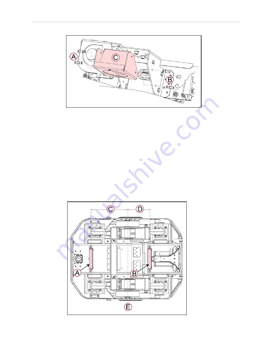
As shown in Figure 9-13, The front HAPS sensor is located 302.4 mm (11.9 inches) in front of
the center line (E), while the rear sensor is located 204.6 mm (8 inches) behind the LD-250's
center line (E).

Содержание LD-60

Страница 1: ...I613 E 04 LD Platform Peripherals User s Guide ...

Страница 2: ... and should not be construed as a commitment by Omron Robotics and Safety Technologies Inc The documentation is periodically reviewed and revised Omron Robotics and Safety Technologies Inc assumes no responsibility for any errors or omissions in the documentation Copyright 2014 2021 by Omron Robotics and Safety Technologies Inc All rights reserved Any trademarks from other companies used in this p...

Страница 3: ...onsibilities 15 Electrical Hazards 16 Pinch Hazard 16 Magnetic Field Hazards LD 60 LD 90 and LDxxxCT Models Only 16 Qualification of Personnel 17 Payload Movement and Transfer 18 Multi AMR Avoidance 18 2 4 Environment 18 General Environmental Conditions 18 Public Access 19 Clearance 19 Obstacles 19 Safety Scanning Laser Emergency Stop 19 Safety System Overspeed Faults 19 2 5 Battery Safety 21 2 6 ...

Страница 4: ...ose Dropoff Mode 35 Patrol Route Mode 36 Localization Goals 36 Screen Logo 37 Contact Information 39 Setting Screensaver 39 Setting Display Language 40 4 4 Operation 40 Screen Initialization 40 Screen Top Bar 41 Left Screen Pane 41 Right Screen Pane 42 Center Pane 47 Relocalization 47 Dropoffs Choose Dropoff Mode only 47 Patrol Route Mode 50 4 5 Specifications 51 Touchscreen 51 Power Supply 51 Cha...

Страница 5: ...nstalled Call Door Box 73 Setting the Arrival Beep Duration 73 Enabling the Queuing Manager for Single AMR 74 Adding Door Areas to Your Map 74 Configuring External I O 76 5 6 Operation 77 Call Door Box Power on 77 Call Buttons 78 Door Boxes 81 5 7 Specifications 82 Call Door Box Specifications 82 Dimensions 82 Communication 83 I O Specifications 83 User Interface 85 5 8 WiFi Compliance 86 General ...

Страница 6: ...ion 117 Components 117 Mounting 118 Connections 120 7 2 Configuration 120 Chapter 8 LD 250 Rear Facing Laser 125 8 1 Laser Location and Orientation 125 8 2 Ignoring Laser Zones 127 8 3 Install the Rear Facing Laser 128 8 4 Configure the Rear Facing Laser 128 8 5 Set the Orientation and Position Values for the Laser 129 Chapter 9 High Accuracy Positioning System 131 9 1 Overview 131 9 2 Components ...

Страница 7: ...e and Marker Application 145 Define Goals 147 9 6 HAPS Software Configuration 147 Robot Physical 147 Robot Operation 147 Goals Tasks 148 9 7 Specifications 149 9 8 Dimensions 150 13732 000 Rev J LD Platform Peripherals Guide 7 ...

Страница 8: ......

Страница 9: ...ion History Revision Code Date Revised Content 01 March 2019 Original release 02 October 2019 Corrections and revisions 03 April 2021 Corrections and revisions 13732 000 Rev J LD Platform Peripherals Guide 9 ...

Страница 10: ......

Страница 11: ...reas where there may be obstacles at various heights that the AMR must avoid These are available as an option for users building their own payload structure l Rear Facing Laser enables obstacle detection in the reverse direction 1 2 Definitions Software used with the platform is described in Mobile Support Software on page 25 Platform The most basic part of the robot It includes the chassis drive ...

Страница 12: ...lation and setup of peripherals for our mobile robots There are additional manuals that cover related topics The following manuals provide information on safety related products advanced configurations and system specifications Table 1 1 Related Manuals Manual Title Description Mobile Robot LD Safety Guide Cat No I616 Describes safety aspect for Omron Robotics and Safety Technologies Inc mobile ro...

Страница 13: ... the equipment l Do not ride on the platform l Do not exceed the maximum weight limit Payload decreases as slope increases l Do not exceed the maximum recommended speed acceleration deceleration or rotation limits Refer to the robot user s guide for specifications l Do not drop the AMR run it off a ledge or otherwise operate it in an irresponsible man ner l Do not allow the AMR to drive through an...

Страница 14: ...utions Alert Levels There are three levels of alert notation used in our manuals In descending order of import ance they are DANGER Identifies an imminently hazardous situation which if not avoided is likely to result in serious injury and might result in fatality or severe property damage WARNING Identifies a potentially hazardous situation which if not avoided will result in minor or moderate in...

Страница 15: ...arrier needs to be continuous at the site so that the AMR cannot drive around or through it to the dropoff Logical Barriers You should also use forbidden areas sectors or lines with several feet of safety zone padding before the actual dropoff to ensure the AMR will not try to drive there These need to be continuous at the site so that the AMR can t plan a path to drive around or between them to t...

Страница 16: ... access the interior of the platform with the charger attached l Immediately disconnect the battery after opening the battery compartment door Avoid shorting the terminals of the battery l Do not use any charger not supplied by Omron Robotics and Safety Technologies Inc l If any liquid is spilled on the AMR power off the AMR clean up all possible liquid and allow the AMR to air dry thoroughly befo...

Страница 17: ... provide the necessary additional training for all personnel who will be working with the system As noted in this and the robot user guides certain procedures should be performed only by skilled or instructed persons For a description of the level of qualification we use the standard terms l Skilled persons have technical knowledge or sufficient experience to enable them to avoid the dangers elect...

Страница 18: ...t a physical method of preventing col lisions such as interlocked gateways or barriers Ultimately it is the end user integrator s responsibility to provide a physical method of preventing collisions NOTE When two AMRs approach each other directly neither can properly determine the other s physical size Their lasers scan several inches into the other s laser slot returning an incorrect distance est...

Страница 19: ... with no forward movement the detection of an obstacle in its path of rotation will not trigger an obstacle detection condition CAUTION PERSONAL INJURY RISK Personnel who work with or around the AMR should not stand close to the AMR when it is turning in place with no forward motion Obstacles If the AMR will be entering high traffic areas the user must take appropriate precautions to alert people ...

Страница 20: ... Absolute Movement Maximums sub section of Robot Configuration the parameters AbsoluteMaxTransVel and AbsoluteMaxTransNegVel can be set to control the maximum velocity of the robot These parameters cannot be set higher than the forward and reverse limit of the hardware platform currently being used Lowering these parameters will prevent the robot from moving at a speed that would cause an overspee...

Страница 21: ...asily navigate the environment then it is safe for the robot Guidelines for safe use l Clean dry floors floors that are regularly swept and routinely kept free of debris and liquids IMPORTANT Since the robot is not water proof IP20 floors must be kept relatively dry as any dampness can cause the wheels to slip This can cause problems for braking as well as navigation Refer to 13849 2 for instructi...

Страница 22: ...t be kept relatively dry as any dampness can cause the wheels to slip This can cause problems for braking as well as navigation Refer to 13849 2 for instructions on how to test the robot in non standard environments If there is any doubt concerning the application ask your local Omron Support to determine if it is an intended use or not Robot Modifications If the user or integrator makes any chang...

Страница 23: ...onment by the proper disposal of WEEE Waste Electronics and Electrical Equipment All electrical and elec tronic products should be disposed of separately from the municipal waste system via des ignated collection facilities For information about disposal of your old equipment contact your local Omron support 13732 000 Rev J LD Platform Peripherals Guide 23 ...

Страница 24: ......

Страница 25: ...ng coordination of a fleet of AMRs through the optional EM It also manages integration with other systems as well as external monitoring setup and control with the MobilePlanner application ARAMCentral ARAMCentral is the software that runs on the EM appliance This software and the appliance combined are referred to as the EM For a fleet the ARAMCentral software manages l the map that all AMRs use ...

Страница 26: ...es support software for the touch screen Call Door Box Support Call Door boxes have one component on the boxes and another on either the EM or on the single robot SetNetGo The SetNetGo OS runs on the AMR core and EM appliance It is the host OS in which ARAM and ARAMCentral run The SetNetGo interface in the MobilePlanner software is used for configuring the Ethernet set tings for the platform upgra...

Страница 27: ...cate the package name for the listing 2 Click the listing to expand the view 3 Click Uninstall 4 You will be prompted for confirmation Click OK to continue 5 Another pop up will be displayed giving the status of the process success or fail Verifying the Status Viewing the Change Log and Viewing Log Output These actions apply to an executable package You can verify the version and current exe cutio...

Страница 28: ...Enable or Disable The default state for enabled vs disabled is controlled by each individual package The same button is used to disable or re enable the package 4 Click OK to confirm that you wish to change 5 If disabled the package will be stopped and will no longer be started at power on ...

Страница 29: ...cludes l Touchscreen with attached bracket l Power supply DC DC converter with bracket l Power cable from core to power supply l Power cable from power supply to touchscreen l Ethernet cable between touchscreen and core l Gasket between touchscreen and AMR mounting surface This protects the touchscreen from vibrations of the AMR l Spacers to prevent the touchscreen from being pressed too hard into...

Страница 30: ...t Mounting Surface Cutout The mounting surface for the touchscreen needs a cutout large enough for the screen to be viewed The four mounting points can either be thru holes in which case the mounting bolts will be visible from the outside of the AMR or you can weld standoffs to the inside of the mounting surface to conceal the mounting hardware CAUTION The touchscreen is not centered horizontally ...

Страница 31: ...er supplied standoffs to the inside of the payload structure surface in which case the screw heads would not be visible from the outside WARNING Use standoffs or spacers to prevent pressing the touchscreen too hard against the mounting surface Excess pressure can cause delayed incor rect or no response when the touchscreen is touched or possibly break the screen s glass The standoffs ensure that t...

Страница 32: ...Touchscreen Mounting D Threaded Standoff on Inside of Panel H Front View 1 Install the gasket between the touchscreen and the inside of the payload structure sur face Line up the gasket with the hole in the payload structure surface so the gasket aligns with the screen cutout 2 Attach the touchscreen to the inside surface of the payload structure If the mounting standoffs are welded to the inside ...

Страница 33: ...0 38 14 63 0 58 83 01 3 27 90 65 3 57 2 x 92 71 3 65 97 64 3 84 2 x Ø 3 99 0 16 0 2 x 15 29 0 6 2 x 16 26 0 64 21 29 0 84 0 5 0 197 11 25 0 44 77 75 3 06 77 98 3 07 Figure 4 4 Power Supply Mounting Bracket Dimensions units are mm inches Connections These connections should be made after the mounting procedure is completed 1 Connect the 5 VDC power cord from the power supply to the touchscreen 2 Co...

Страница 34: ...sure that l the IP address subnet doesn t conflict with the Wireless Ethernet IP subnet l Interface mode is set to Accessory l DHCP Server for Accessories is set to Enable l DHCP IP Range is large enough to provide IP addresses for all connected devices Figure 4 6 Accessory and DHCP Server for Accessories Enabled 4 3 Configuration You configure the touchscreen s appearance and behavior with the Mo...

Страница 35: ...riority This is accessed under Pages ChooseDropoffPage You can enable high priority dropoffs which will be serviced before normal priority dropoffs The Operator can specify that a goal is high priority when it is being selected for the upcoming dropoff AllowHighPriorityDropoffs This allows some dropoffs to be specified as high priority This is enabled by default and you can disable or re enable it...

Страница 36: ...u also need to specify if the AMR will start its patrol automatically or if it requires an Operator to press Go Select Pages PatrolRoutePage l In RouteName enter the route to be patrolled l Check AutoStartRoute for the AMR to start its patrol as soon as the Patrol Route screen is displayed the AMR has finished booting Localization Goals You need to configure at least one localization goal You can ...

Страница 37: ...anner select Config Robot Interface Touchscreen From there use ChooseLocalizationPage to set LocalizationButtonCount to the number of loc alization goals you want and then specify the GoalName and ButtonLabel for each Figure 4 7 Localization Goal Parameters Screen Logo In MobilePlanner select Config Robot Interface Touchscreen From there use Style Appearance A logo is displayed in the upper left c...

Страница 38: ...File Download Upload 2 Open the AMR Configuration window and choose Robot Interface Touchscreen 3 Edit the SmallLogo parameter a Click the file select button to open the file chooser b Select the newly uploaded file c Click Open 4 Click Save to save the configuration NOTE If the SmallLogo field is left blank the default Omron logo will be dis played NOTE If a different version of the same file nam...

Страница 39: ...wContactPage check box l Enter appropriate information in ContactName and the fields following it Setting Screensaver In MobilePlanner select Config Robot Interface Touchscreen From there use Screensaver If the AMR is in motion when the screensaver comes on it will use the Busy icon and display a status message where it s going If the AMR is not in motion it will display the Available icon The rou...

Страница 40: ...anguage is used for the display from a dropdown box in the MobilePlan ner software NOTE Some messages from the AMR will be in English regardless of the lan guage set here These include status and mode messages From MobilePlanner select Config Robot Interface Language Location Select RobotLanguage which has a dropdown selection box This parameter is not touchscreen specific so it may affect other d...

Страница 41: ...nal strength the name of the AMR and the battery state of charge If the AMR is con nected to an EM it will also be specified here Left Screen Pane The screen logo is displayed in the upper part of the left pane This doesn t change regardless of the mode you are in Below the screen logo the AMR status is displayed first graphically and below that in text Figure 4 11 Screenshot Showing Top Bar and L...

Страница 42: ...time the AMR is scheduled to wait before continuing to its next goal l If you press Stay while the AMR is moving it will stop and stay for 1 minute NOTE The Stay count down timer can be zeroed at any time by pressing Go at the bottom of the center pane The screensaver can be set up to behave the same way the Stay button does so that pressing the screensaver adds 1 minute to the time the AMR will w...

Страница 43: ...stination but does not have a payload Please load an item or cancel the dropoff This will be displayed in the screen s center pane NOTE The payload parameter section will not be displayed unless the payload slots at the top of the Payload Present Messages and Behavior are set to a non zero value The Home screen also has an entry for relocalizing a lost robot from the touchscreen See Relocalization...

Страница 44: ...n a red circle on the Status button See the preceding figure Figure 4 14 Status Tab and Sub menu o Alerts shows an abbreviated list of all active alert messages Touching on a specific message will display that full message o Robot shows robot status such as the IP address what it is currently doing and its mode Position Details within the Robot Status screen shows the robot s position head ing vel...

Страница 45: ...he screen without it interpreting that as input The screen stays locked for one minute and then returns to normal function l Help shows information on the installed software and contact information NOTE No contact information will be displayed unless it is set up in the MobilePlanner software Figure 4 16 Help Contact Information 13732 000 Rev J LD Platform Peripherals Guide 45 ...

Страница 46: ...shooting Replay Recorder The replay recorder will record data for troubleshooting Once the start page is opened you just click Start When you are done recording click Stop The Duration and Replay File fields are filled in by the recorder After the recording is completed you will need to use the MobilePlanner software to download the file generated Figure 4 17 Replay Recorder Start Page ...

Страница 47: ...goals if you like See Localization Goals on page 36 If the AMR becomes lost the touchscreen will automatically select the Home tab from the right pane and display a message indicating that the AMR is lost It will also offer an option to Recover 1 Press Recover 2 Follow the on screen instructions You will be instructed to manually move the AMR to a localization goal and then tell the software which...

Страница 48: ...e the job for this goal can be canceled but the priority cannot be changed l Interrupted such as Stay being pressed or a fault occurring will be dark blue with an orange border At this stage the job for this goal can be canceled but the priority cannot be changed l Completed or Canceled dropoff buttons will revert to Ready status Operators can use this pane for entering the goals where they want t...

Страница 49: ...tton is displayed Touch ing this pop up will toggle the priority for the goal or job between high and normal priority See the following graphic When a job is assigned high priority its dropoff button will display a visible high priority indicator A high priority job will be serviced before all normal priority jobs even if those jobs were entered at an earlier time This means that if you press Goal...

Страница 50: ...ends that wait and the button border stays green The job isn t interrupted from the queuing man ager s perspective the wait task has just been prolonged Go Button The bottom of the center pane in Dropoffs and user selected Home mode is a Go button This zeroes the countdown timer and causes the AMR to immediately proceed to its next goal This can be used in conjunction with the Stay button to pause...

Страница 51: ...ack bordered cover lens TFT Display TFT LCD panel 18 24 bit RGB parallel interface 7 0 in WVGA Wide Viewing Angles 5 Touch Backlight Constant current LED supply Power Input 5 VDC supplied through power connector Power Consumption 6 5 W maximum Operating Temperature 0 to 60 C Power Supply MeanWell SD 15B 05 15 W 18 36 V input 5 V output 13732 000 Rev J LD Platform Peripherals Guide 51 ...

Страница 52: ...ed Power 15 W Voltage Adj Range 4 75 5 5 VDC Voltage Tolerance 2 0 Input Voltage Range 18 36 VCD DC Current Typ 1 9 A 12 VDC Protection Overload 105 160 rated output power Over Voltage 5 75 6 75 V Environment Working Temp 10 to 60 C Working Humidity 20 90 non condensing Storage Temp 20 to 85 C Storage Humidity 10 95 non condensing ...

Страница 53: ...ware and soft ware The differences are covered in this chapter Refer also to the EM User s Guide which covers the EM hardware and software required for managing multiple AMRs a fleet and the FLOW Core User s Guide which covers software needed for configuring and managing a fleet or an AMR A B Figure 5 1 Call Door Box A Red LED and B Speaker Hole 13732 000 Rev J LD Platform Peripherals Guide 53 ...

Страница 54: ... only one AMR NOTE Call buttons cannot be used for AMRs that are in Patrol Route mode Door Boxes Door Boxes are used to issue a request to open a closed door that is equipped with a door actu ator so an AMR can pass through it One door box is required for each door to be opened NOTE It is also possible to use a door box as two generic digital inputs and two generic digital outputs In this case the...

Страница 55: ...uts can be wired to an external device such as a beeper or light to signal the status of the job Automatic control of the outputs is configured with the parameter AutoIo which can be set to Neither Output1 Output2 or Both the default If an output is configured for Automatic control the following table shows the behavior for the output Job Status Output1 Output2 Idle or Cancel OFF OFF Request Activ...

Страница 56: ...ure 5 2 Back of Call Door Box Showing Ethernet and VDC Power Supply and Connector The call door boxes come with a 12 V power supply which connects to the back of the call door box The connection is circled near the bottom of the preceding figure The power supply connector can only be inserted one way into the back of the box Figure 5 3 Power Supply Connector DIP Switch A DIP switch with four posit...

Страница 57: ...aults Position 3 DP3 Not Used Not used Not used Position 4 DP4 Control sound Sound enabled Sound muted Position 2 on the DIP switch resets the LAN and WLAN settings and also provides a means to access the built in web interface for configuration Position 4 can be turned ON muted in situations where audio is not appropriate Door Actuator Door Box only This is user supplied and must be capable of op...

Страница 58: ...Call Door Box Eth E ARAMCentral M Call Door Node Software F Call Door Host Software N Call Door Box WiFi G Access Point There are two components to the Call Door box software One runs on each Call Door Box The other component runs on the EM if there is one or on the AMR core for a single robot install ation Both are included in the FLOW Core The software l Manages discovery and connection to newly...

Страница 59: ... connector into the back of the call door box Refer to Figure 5 2 Figure 5 3 and Figure 5 4 2 Connect your PC to the Ethernet port on the back of the call door box Use a straight through Ethernet cable The port is shown circled near the top of Figure 5 2 3 If you have not changed the call door box default IP address or you have reset it back to the default configure your PC to use IP address 1 2 3...

Страница 60: ... need to switch the DIP switch position 2 back to OFF and then power cycle the call door box Using the push button a Remove power from the box b Re apply power to the box All the LEDs will come on The red LED will be on but not blinking c Wait 60 seconds d Press and hold the button If the lights go out before you press the button you will need to recycle power to start the process over While press...

Страница 61: ...the configuration screens You can nav igate to these screens by selecting l Wired Ethernet or Wireless WiFi and l Interface or Link and l Status or Configuration or Scan If you select Wireless and Link Scan becomes available in the third row These selections are at the top of the center pane in all of these screens There are a total of nine screens that you can access through the Network Tab NOTE ...

Страница 62: ...terface Figure 5 8 Wired Interface Configuration Screen 1 Enter an IP address for this call door box Each call door box is a node on the network and needs its own IP address An explicit mask may be entered but is not required 2 Click Store Permanent to write the configuration change to flash The information panel will reflect the changes you made 3 Put a temporary label on the front of the call do...

Страница 63: ...creen Wired Ethernet Link Configuration This lets you configure the link Figure 5 10 Wired Link Configuration Screen Wireless WiFi Interface Status This shows the status of the wireless network interface on the call door box Figure 5 11 Wireless Interface Status Screen 13732 000 Rev J LD Platform Peripherals Guide 63 ...

Страница 64: ...Change the static IP Address to fit your wireless network 2 Click Store Permanent to write the configuration change to flash The information panel will reflect the changes you made 3 Put a temporary label on the front of the call door box with its IP address This will be useful when you need to enter the IP address into MobilePlanner Wireless WiFi Link Status This shows the wireless link status Fi...

Страница 65: ...Profiles Tab Use the WLAN Profiles tab in the left pane to access the WLAN Profiles page You are given the choice of either default_infrastructure or adhoc Choose default_infra structure which will use your access port rather than establishing a peer to peer network Ad hoc is only used for temporary setups with a very small number of peers WLAN Profiles This lets you select which of the two profil...

Страница 66: ...eckbox and then click Default_Infra structure_Profile which is a link to the next screen WLAN Profiles Default_Infrastructure_profile This screen lets you configure the default_infrastructure profile Figure 5 17 WLAN Default_Infrastructure Configuration Screen 1 Enter a Network Name SSID and Passphrase 2 Test the connection by clicking Apply Temporary then Test Connection ...

Страница 67: ...os ition 2 to OFF b Power cycle the call door box 5 Wait for at least one minute then ping to test the wireless connection Resetting a Call Door Box WiFi or Wired 1 Remove power from the call door box 2 Set the DIP switch position 2 to ON Refer to DIP Switch on page 56 3 Power on the call door box This will reset the box to factory defaults DIP switch settings are not affected 4 Set the DIP switch...

Страница 68: ... diameter is 3 5 mm 1 8 in The length of the screws depends on the type of wall and whether you are using one or two wall mounts Refer to Dimensions on page 82 For two wall mounts reverse the mount nearest the wall as shown in Figure 5 20 and Figure 5 21 2 Remove the two screw covers from the call door box Press down on the center of each cover and slide it out away from the box 3 Plug the 12 VDC ...

Страница 69: ...tputs The I O for door boxes can be configured in the MobilePlanner software The behavior of the I O for call buttons is hard coded See External I O on page 55 6 Attach the box to the wall mount using four supplied self tapping screws See the fol lowing figure Figure 5 20 Attaching the Call Door Box to its Mount Two Wall Mounts Shown 7 Reattach the two screw covers to the box Press down on each co...

Страница 70: ...ion is required Overview of Tasks l Enter the IP address of each Ethernet device l Assign a goal to each call button l Enable the Mobile Call Button GPIO software l For call buttons o Configure the parameter BeepSeconds to set how long the node beeps when the robot arrives This parameter applies to all call buttons o For a single AMR installation enable the Queuing Manager l For door boxes o Confi...

Страница 71: ...that you assigned to the box o Type is auto populated with either CallButton or Door o GoalName call buttons only Enter the name of the associated goal o Priority call buttons only Enter the priority to assign to the associated goal This field will only be visible if the Show Expert Parameters box is checked This is an integer value that represents the priority of the pickup request The higher the...

Страница 72: ... you decide to install multiple call buttons or door boxes before configuring them refer to Identifying an Installed Call Door Box on page 73 5 Enable the Mobile Call Button GPIO software using SetNetGo Figure 5 23 Enabling the GPIO Software a Access MobilePlanner SetNetGo b Select Software Manage Installed Software c Locate the package name Mobile Call Button GPIO Software from the listing Click ...

Страница 73: ...pop up will identify which button was pressed so you can find the correct items to con figure in the MobilePlanner software Door Boxes If you have installed multiple door boxes without adding their Door area data to the map you can use the box push button to identify the box Pressing the push button causes a pop up mes sage to be displayed in the MobilePlanner software identifying which door box w...

Страница 74: ...ePlanner Config Robot Operation Queuing Manager enable Queuing Man ager if you have only a single robot A call door box button press will queue a PICKUP job at the goal associated with the call door box Figure 5 25 Enabling the Queuing Manager Adding Door Areas to Your Map Configuring an Output Signal An output signal from the door box needs to connect with the door actuator NOTE None of the follo...

Страница 75: ...abled 1 MobilePlanner Config Robot Operation 2 Map Features o SingleRobotSector o Doors These are both check boxes no values are needed NOTE The goals and DoorSwingSector must exist and the door output must be configured before you can create a Door area You will have to estimate where to place the Door area See Hints and Tips for Door Areas Door Goals on page 76 Decide where the Door area will go...

Страница 76: ...ing on your door You should time this and add a few seconds as a buffer to ensure that the door is out of the way The default is 10 seconds f Select the DoorSwingSector from the drop down in the SwingSector field The MobilePlanner software will not let you finish creating a Door area if it does not have two Door goals an output and a DoorSwingSector 4 If multiple AMRs might try to use a door at th...

Страница 77: ...mine what happens when the input switches ON o Suffix Suffix appended to the alias when the input switches on If an alias is not specified then the suffix is appended to the raw name o Count Number of responses when Device xx yy zz _Input_1 switches on o Type1 A response when the Input_1 switches on This field will not be displayed if Count is zero l OffList List of responses when Device xx yy zz ...

Страница 78: ...t Network Switch K Ethernet Call Button E ARCL L WiFi Call Button AMR Request Sequence of Events NOTE Call buttons have two optional outputs that can be used for an external beeper light or other device By default these are both OFF Changes in their states are noted in this sequence Call buttons are fully functional without using these outputs Regardless of the method of communication being used b...

Страница 79: ...h the button won t blink A ring of LEDs around the push button will light and count down the distance remain ing for the AMR to reach the goal When it gets within a certain distance the cor responding LED will go out See the following figure Figure 5 27 Call Door Button Lights NOTE The HERE LED will be solid when the AMR is within 5 M and blink when the AMR has arrived NOTE The LEDs will display t...

Страница 80: ...es the button before the AMR has arrived it sends a request to can cel the job This can be at any stage of the request sequence before arrival When the queuing manager receives the request to cancel via the call door box host soft ware it cancels the job and instructs the host software to send a signal back to the call button All of the LEDs including the push button LED will blink briefly and the...

Страница 81: ...ntirely set to beep for a specified number of seconds or set to beep continuously until the AMR is dis missed l Beeps briefly when request is canceled Red Error LED l OFF good connection l Blinking host connection lost Door Boxes NOTE Except during power up most distance LEDs and the push button LED are not used for a door box The HERE and 40m LEDs will be lit 1 When an AMR reaches the entry goal ...

Страница 82: ...close door request via the host software to the door box 8 The door box signals the door actuator to close by turning the door output off 9 The door actuator closes the door 10 The host software sets the door box back to a wait ready state 5 7 Specifications Call Door Box Specifications Each call door box is powered by 12 VDC Power consumption on average is 0 5 A or 6 W Dimensions 141 37 5 57 50 1...

Страница 83: ...Communication The call door box has options for the following communication methods l Wireless Ethernet 802 11 o 802 11a b g n o 2 4 GHz o 5 GHz l Wired Ethernet I O Specifications Inputs l 100 mA circuit protection l User supplied voltage free contacts l Inputs and outputs are configured in the MobilePlanner software See Configuring External I O on page 76 13732 000 Rev J LD Platform Peripherals ...

Страница 84: ...a beeper light or other use Both inputs act as external push button presses NOTE A call button can be turned into a door box with the DIP switch in which case the I O can be configured by the user When used as a door box Output1 is dedicated as a signal to the door actuator to open the door Only Output2 is available to the user Output1 Output2 Input1 Input2 Call Button ON when In Progress ON for 1...

Страница 85: ...l Eight LEDs in a circle around the push button to indicate the AMR distance from its goal HERE 5m 10m 20m 40m 80m 150m 300m l Beeper to indicate that the AMR has arrived at the goal or request is canceled This can be configured or turned off in the MobilePlanner software l Red error indicator LED indicating loss of connectivity with the host l QR code containing link to Omron web site and call bu...

Страница 86: ...e Irvine CA 92618 USA Tel 949 453 3990 Fax 949 450 7249 FCC and IC WiFi P N 13029 802 WiFi Lantronix Contains PremierWave EN Embedded Device Server Conforms to FCC Part 15 247 15 407 Class B This device complies with Part 15 of the FCC Rules Operation is subject to the following two conditions 1 This device may not cause harmful interferences and 2 this device must accept any interference received...

Страница 87: ...e AMR Door Box l WiFi CDB WiFi infrastructure EM l Wired CDB EM Unsupported Configurations Single AMR l WiFi CDB AMR This has to go through the WiFi infrastructure before going to the AMR Fleet l WiFi CDB AMR EM WiFi infrastructure AMR For a fleet all communication must go through the EM 13732 000 Rev J LD Platform Peripherals Guide 87 ...

Страница 88: ......

Страница 89: ...os that affect which sections of this chapter you will need l Acuity localization has been ordered with a platform and a factory designed payload structure l Acuity localization has been ordered with a platform to be installed on a payload struc ture designed by you l Acuity localization has been ordered as a kit to be installed as an upgrade to an exist ing platform on a payload structure designe...

Страница 90: ...17 mm hole must line up with the AMR s direction of travel NOTE For localization the holes and camera need to be aligned within one degree of rotation about the X and Y axes of the platform See the fol lowing figure for hole orientation A Figure 6 1 A Direction of Travel Hole Pattern 6 1 Tasks l Install camera assembly l Connect power and data cables between camera and platform core l Enable Acuit...

Страница 91: ...d Only needed if the Auxiliary Ethernet port on the platform is being used by another peripheral A B C D E F J H G Dire ction of Trav el Om ron Ad ep t Te ch no log ies Inc 45 50 No rri s Ca ny on Ro ad 15 0 Sa n Ra mo n CA 94 58 3 Mod el Acu ity P N 13 70 0 00 0 Figure 6 2 Acuity Camera Components Callout Description Callout Description A Neutral Density Filter F Bracket B Foam Dust Seal G Direct...

Страница 92: ...into the single clinched nut in the cam era enclosure base NOTE It will simplify configuration by minimizing the Theta offset if you mount the camera base so that the hole with the clinched nut is facing toward the left of the AMR Y l Mount the base to the mounting location using an M4 x 12 mm socket head screw You may need to use a longer screw depending on the thickness of your mounting location...

Страница 93: ...Detail of Base Mounting Holes H Mounting Location 2 Mount the camera bracket to the camera enclosure base The bracket will only fit on the base one way Attach the camera bracket firmly to the base using 3 M4 x12 mm socket head screws You may need to use longer screws depending on the thickness of your mounting loc ation Washers and lock washers are recommended though not shown here 3x M4 x 12 A B ...

Страница 94: ... inside your payload structure through the payload structure surface and camera enclosure base and into the three clinched nuts in the bot tom of the camera bracket There is a sticker on the camera bracket that shows the direction of travel of the AMR See the following figure Verify that the arrow on the sticker is pointing toward the front of the AMR Direction of Travel 4550 Norris Canyon Road Sa...

Страница 95: ... Through Holes Equally Spaced at B Through Hole and C Label on Back units are mm inches 3 Attach the camera to the camera bracket a Attach the camera cables to the camera before mounting the camera Refer to Camera Connections on page 96 b Attach the camera to the mounting bracket using three M3 x 4 mm button head screws NOTE The camera needs to be mounted as high in the bracket as possible without...

Страница 96: ...ity camera s signal cabling is sensitive to inter ference from noise and its power supply is sensitive to ripple Route sig nal cables to avoid interference If your payload s power demand is high or you need to add other devices to the AUX power circuit carefully test Acuity operation before deploying and contact your local Omron Support if you have problems a Feed the Hirose end of the power cable...

Страница 97: ...r power connector available for other uses f Connect the Ethernet cable from the camera to the Auxiliary Ethernet port on the core NOTE If other peripheral items such as the touchscreen interface also require the use of the Auxiliary Ethernet connection then a fast Ethernet switch will be required user supplied 4 Attach the tube onto the base The threads at the bottom of the tube are coarse and ma...

Страница 98: ...aching the Tube to the Base A Tube and B Camera Enclosure Base 5 Install the foam dust seal and ND filter a Insert the foam seal around the camera lens and press into the tube until the seal sits on the camera body b Thread the neutral density filter onto the camera enclosure body tube ...

Страница 99: ...g Acuity localization as an upgrade to an existing system Install the Acuity supporting libraries first This package will either be supplied with the Acu ity order or it can be obtained through our applications engineering staff Refer to SetNetGo Managing Software Packages on page 26 6 4 Setup Enabling Acuity In MobilePlanner 13732 000 Rev J LD Platform Peripherals Guide 99 ...

Страница 100: ...es Figure 6 11 Enabling Acuity in the MobilePlanner Software These will only be visible if the Show Expert Parameters box is checked To make a change you will need to click and drag the desired parameter from the expert Parameters tab into the Configuration tab For instances where only Acuity operation is desired both boxes should be checked This will cause the AMR to use only the Acuity camera fo...

Страница 101: ...of tasks to be used in the AMR s map Among these new tasks will be l DisableLaserLocalization l DisableLaserLocalizationCancel l DisableLightLocalization l DisableLightLocalizationCancel These tasks can be used to selectively switch between Acuity and laser localization NOTE These tasks cannot be used while the AMR is moving Place the tasks in a macro in a virtual door or after a goal where the AM...

Страница 102: ...Command drop down arrow and click PopupCameraSerialNumber You will see a popup with the camera serial number Figure 6 13 Getting the Camera Serial Number 4 Load the camera calibration file which was provided with the Acuity system from MobilePlanner by selecting File Import Config then navigating to the location of the file on your PC The name of the calibration file will match the serial number o...

Страница 103: ... the position of your camera with respect to the AMR into the MobilePlanner software Refer to the following figure 697 27 4 Z 0 X Y Z X 0 Y 0 theta Z 0 17 5 0 69 5 5 0 22 A X 0 Y 0 500 19 7 Figure 6 15 Measuring the Camera Platform Offsets A At Sensing Plane of Camera units are mm inches 13732 000 Rev J LD Platform Peripherals Guide 103 ...

Страница 104: ... will have its rear side with threaded holes for mounting it facing Y of the AMR the AMR s left side This will result in a CameraOffsetTh theta of 0 If this is not the case then a theta offset must be applied For example if the back of the camera is facing the rear of the AMR the Cam eraOffsetTh will be 90 as a counter clockwise rotation is positive 4 Finally measure the tilt of the camera with re...

Страница 105: ... base as the slot for the camera bracket The level and base should have been delivered to you this way See the following figure A B Figure 6 17 Level Base A USB Port and B Camera Slot It will only fit one way with the slot in the plastic base of the level fitting over the back side of the camera mounting bracket The slot is called out in the pre ceding figure 5 Enter the values directly from the d...

Страница 106: ...o make a map Refer to the FLOW Core User s Guide The tasks involved are l Make a scan of the operating space while driving the AMR with the joystick NOTE It is a good idea to have the automated docking station installed before you make the scan The distinctive angle and shape of the front of the docking station will be useful in locating and setting it up in the map l Load that scan from the AMR i...

Страница 107: ...ngLightHeight parameter this is strictly for display purposes and does not affect AMR operation If there are areas within the environment that have different light heights you do not have to scan the space again Pick one light height to be first and enter the values for Min and Max light height into the configuration before scanning You can adjust these later and multiple maps can be processed fro...

Страница 108: ...108 LD Platform Peripherals Guide 13732 000 Rev J 6 5 Making a Map of Your Environment Figure 6 19 Sample Mapping Strategy Figure 6 20 Resultant Map ...

Страница 109: ...scan will be processed first followed by the extra processing for the lights If all of the parameters were set properly the light blue light items will be visible on the map overlaid on the points and lines from the laser data Figure 6 21 Initial Map with both Laser and Light Data 2 If you are satisfied with the map NOTE Check that the lights are where you think they should be and their general di...

Страница 110: ...ate multiple maps from your one scan using different light heights You will then insert the appropriate map sections into the initial map which will add the lights from the adjusted light height range This needs to be done for as many different light heights as you have in the environment Creating a Revised Map These steps are performed after saving the initial map which included lights within the...

Страница 111: ...uity Localization Figure 6 22 Selecting a Map File to Insert Figure 6 23 Inserted Map 4 Click and drag the purple highlighted map to line it up with the initial map 13732 000 Rev J LD Platform Peripherals Guide 111 ...

Страница 112: ...oom in very close You should be able to align the two laser maps perfectly as they are identical maps with only differences in the lights Figure 6 24 Zoomed in Insert Map c Click Insert to complete the insertion 5 Zoom back out and use the Region Tool from the Insert Map Tools toolbar to click and drag a rectangular region that includes the lights you want inserted ...

Страница 113: ...dvanced Options check the boxes l Include user created map items i e non data types l Retain overlapping items of the same type in the containing map NOTE If lights of different types are physically behind one another in the environment it may be necessary to scan that space twice once with just each light type exclusively This means that you would have to turn off lights at one height then scan a...

Страница 114: ...ools toolbar b Click Save on Robot then select the IP address of either the AMR or the EM if your AMR is part of a fleet NOTE After mapping DO NOT manually move resize reorient or otherwise modify the light items on the map If lights did not turn out as expected some combination of parameter changes should allow reprocessing of the scan in order to achieve better results 6 6 Operation Localizing M...

Страница 115: ...p enable their display by using the Map Map Data Light Items menu item in MobilePlanner From Map Robot Data Other Robot Data l LightMatch compares the lights that an AMR has detected with its camera to the lights on the map Light matches are displayed in green l LightMisses shows lights that are seen by the camera and meet the criteria for a proper light but which do not match a known light on the...

Страница 116: ......

Страница 117: ...rs should not be used as the primary method for avoiding negative obstacles It is intended to be used as a secondary method of detection with the primary method being traditional safety techniques to aid avoiding negative obstacles Primary methods include blocking off areas with missing floor tiles staging safety equipment near areas missing floor tiles and restricting traffic to dangerous areas N...

Страница 118: ... strain Clearance for the laser guard provided with the kit should also be considered when choosing a mounting location It is recommended to mount the side lasers at a position that prevents detection of any part of the AMR or the payload structure Care must also be taken that the laser is ori ented properly to ensure correct operation The side lasers must be mounted in an orientation so that thei...

Страница 119: ...e laser assembly are provided below 110 Figure 7 2 Side laser assembly rear dimensions units in mm 60 147 4X 4 5 MOUNTING HOLES 79 6 89 COVER 165 80 Figure 7 3 Side laser assembly top view dimensions units in mm 13732 000 Rev J LD Platform Peripherals Guide 119 ...

Страница 120: ...orque of 1 0 N m Connections The harness should be connected after the physical mounting procedure is completed The lasers connect to the Aux Sensor connector located on the upper front of the platform core using the supplied W cable This allows you to use one port for both side lasers and the low front laser 7 2 Configuration The parameters for the side lasers are set using the MobilePlanner soft...

Страница 121: ...r scans an area of 270 degrees This area should be modified so that the laser does not sense parts of the AMR Zones entered here will be excluded from the search area A Figure 7 5 Left Side Laser Laser 4 A This Laser is Flipped Upside Down The format for the angles is startangle1 stopangle1 startangle2 stopangle2 etc Readings inside these angles will be ignored An example would be 20 180 45 180 l ...

Страница 122: ...llows the laser to be configured for the application s specific environment In select cases you will need to modify the Cumulative parameters Sensor readings are often held on the map so that the robot remembers an obstacle even when it cannot be actively seen The length of time that the robot will remember these readings is MaxSecondstoKeepCumlative In dynamic environments where the robot will be...

Страница 123: ...unted on the left side of the robot The easiest way to do this is to turn off one of the lasers using the LaserAutoConnect parameter and watch the laser readings in MobilePlan ner In the image below you can see that the enabled side laser is showing readings on the left side of the robot Figure 7 8 Checking the Left Side Laser 13732 000 Rev J LD Platform Peripherals Guide 123 ...

Страница 124: ......

Страница 125: ...g laser kit consists of the following items Figure 8 1 Rear facing Laser Kit Callout Part Number Description A 14851 000L Debug Port DB9 adapter cable B 14682 000L TiM to DB9 adapter cable with Aux Power split C 13438 000 TiM 510 laser firmware version 3 15 8 1 Laser Location and Orientation To configure a laser into MobilePlanner you must know its position and orientation in rela tion to the AMR ...

Страница 126: ...nning field 3 Scanning field arc in this case 200 degrees Figure 8 3 Laser Sensing Plane Callout Description 1 Cap over the laser s lens 2 Lens return zone detects returned bounced laser light pulses This is approx 10 mm wide 3 Lens emitter zone sends laser light pulses This is about 8 mm wide and is the loc ation of the scanning field plane The emitter zone is the point from which you measure the...

Страница 127: ... the software This will make sure that the AMR or its payload are not detected as obstacles preventing vehicle motion Figure 8 4 Calculating Values for Ignored Laser Zones Callout A Negative direction Clockwise B Positive direction Counterclockwise C Laser with a 270 degree scanning plane D Scanned segment of the 270 degree plane E Ignored segment of the 270 degree plane When calculating these val...

Страница 128: ...s that you have put the AMR into a safe state for mechanical and electrical work Install the lasers as follows 1 Remove necessary components to access the LD 250 Core 2 Connect the cable as follows a Connect the DB9 plug to the LD 250 Core s Debug port b Connect the Molex plug to the LD 250 Core s AUX_20V port 3 Mount the laser facing in the appropriate direction typically the opposite direction o...

Страница 129: ...stem start up 5 Enter the laser s mounting location coordinates a LaserX front to back b LaserY left to right c LaserZ height from floor 6 If required use the LaserIgnore parameter to specify ignored segments of the scan field 7 If required set the LaserFlipped parameter to true if the laser is inverted or is on the left side of the AMR 8 If required set the value of LaserTH depending on the direc...

Страница 130: ......

Страница 131: ...tions with multiple places where you want the AMR to stop you would use a con tinuous tape strip for all stops with one marker at each stop one goal for each marker and an Engage task for each goal The goals would all be at the same location near the start of the tape The Engage tasks allow an AMR to follow the tape performing tasks from the successive goals without ever having to return to the lo...

Страница 132: ...stalled B Rear Sensor E Front Sensor C Rear Sensor Bracket F Front Sensor Bracket WARNING MAGNETIC FIELD MEDICAL IMPLANT RISK Magnetic fields can be hazardous to medical implant wearers Medical Implant wearers should stay at least 30 cm 12 inches away from the under side of the Platform Single and Dual Sensor Installation Part 1 1 Remove the side covers on both sides of the platform 2 Remove the p...

Страница 133: ... Dual Sensor Installation and then perform the steps in Single and Dual Sensor Installation Part 2 on page 136 Single Sensor Installation A single sensor goes in the forward position of the AMR 1 Remove two M5 stainless socket head cap screws split lock washers and flat washers from the underside of the platform See the following figure for the locations of the screws Save the screws and washers f...

Страница 134: ...of the AMR with the cable between the bracket and the platform The sensor will already be attached to the bracket Use the M5 screws and washers previously removed Use Loctite 243 3 Route the sensor wires back to behind the right drive wheel as shown Figure 9 4 Front Cable Route Shown in Yellow 4 Install two cable tie anchors to the underside of the platform along the path of the ...

Страница 135: ...the AMR with the cable between the bracket and the platform Its cable will be labeled FRONT The cable will have two branches each attached to a sensor and bracket assembly Use the screws and washers previously removed Install the M5 screws with Loctite 243 The sensor will already be attached to the bracket 3 Attach the rear bracket assembly to the underside of the AMR Use the M5 socket head cap sc...

Страница 136: ...ed to the next section Single and Dual Sensor Installation Part 2 Single and Dual Sensor Installation Part 2 1 Route the sensor wires both data and power up through the platform chassis just behind the right drive wheel and through the cutout shown in the following figure Figure 9 7 Cutout in Payload Bay for Cables Cable tie the cables to the anchors previously installed behind the right wheel See...

Страница 137: ...upper rear core Figure 9 8 Upper Rear of Core Showing AUX PWR Port 4 Plug the sensor power connector into one branch of the splitter cable This can power one or two sensors 5 Plug the RS 232 connector s into the upper front of the core Figure 9 9 Upper Front of Core Showing RS232 Ports The front sensor plugs into RS 232 1 13732 000 Rev J LD Platform Peripherals Guide 137 ...

Страница 138: ...protect the LD 250 from damage l Straps or other method of securing the LD 250 safely while tipped on its side l Single or dual HAPS sensor kit If you are installing dual sensors you also require the supplied splitter cables that provide power to both sensor assemblies Preparing the LD 250 to Install HAPS Sensors Prepare the LD 250 so that you can tip it on its side This might require removing the...

Страница 139: ...nd the speaker assembly B toward the front of the LD 250 as shown in Figure 9 11 Figure 9 11 LD 250 On its Side A Showing the Location of Speaker Assembly B 6 Use a 4 mm hex driver to remove the two pairs of M5 screws and washers A and B in Figure 9 12 that retain the loudspeaker assembly to its mount Carefully pull out the speaker assembly C in Figure 9 12 until you can reach and dis connect both...

Страница 140: ... and dual HAPS sensor installation If you intend to install only a single sensor ignore the steps identified as Dual Only The photographs used in the procedure show additional components removed from the LD 250 This is for clarity only you do not need to remove any additional components at this point As shown in Figure 9 13 The front HAPS sensor is located 302 4 mm 11 9 inches in front of the cent...

Страница 141: ...able as shown in Figure 9 14 over the bracket and up the side of the chassis adjacent to the caster mount Use a zip tie to secure the cable to the available cable tie mounts positioned on the chassis leaving no slack Figure 9 14 LD 250 Front HAPS Cable Routing Over the Sensor Bracket 3 Feed the cable behind the speaker mount as shown in Figure 9 15 Use a zip tie to secure the cable to the availabl...

Страница 142: ... 4 Installation on the LD 250 Figure 9 15 LD 250 Front HAPS Cable Routing Behind the Speaker Mount 4 Pass each RS232 connector one at a time through the oval hole in the side of the chassis as shown in Figure 9 16 Feed the cable through leaving no slack ...

Страница 143: ...on the upper front of the LD 250 Core B in Figure 9 17 7 Connect the Molex Mini fit plug power to the user power connector on the back side of the LD 250 Core D in Figure 9 17 8 Dual Only Use a 4 mm hex key and the two supplied M5 socket head cap screws and washers to install the sensor marked Rear at location B in Figure 9 13 Make sure that the sensor is facing forward toward the front of the LD ...

Страница 144: ...from sagging E Into the back of the speaker mount F Pass each RS232 connector one at a time through the oval hole in the side of the chassis 10 Dual Only Pass the connectors up through the oval slot in the payload bay A in Fig ure 9 17 11 Dual Only Connect the rear sensor s DB9 plug to port RS 232 2 on the upper front of the LD 250 Core C in Figure 9 17 12 Dual Only Connect the rear sensor Molex M...

Страница 145: ...oth LD 250 and for LD 60 LD 90 and LD xxxCT models in hybrid fleets because of their different sizes and turn radius To determine the distance between the LD platform and its final alignment goal such as a machine with which it interfaces Refer to the LD model User s Guide to obtain the exact dimensions of the platform For example for the LD 60 LD 90 and LD xxxCT models the platform body is 499 mm...

Страница 146: ...the markers upside down relative to the tape If you use tape with North up rather than the South up tape ensure that the markers are applied with their South side up The recommended marker length is 300 mm Shorter markers can be used if the AMR is oper ating at slower than default speeds 500 mm second The AMR will stop with the front sensor at the front end of the marker Note the model dependent l...

Страница 147: ...re configured using the MobilePlanner software Robot Physical 1 Go to MobilePlanner Config Robot Physical 2 Check the Show Expert Parameters check box 3 For GuideSensor_Front a Check the AutoConnect check box b Set the Port parameter value to dev ttyUSB9 4 For GuideSensor_Rear when a second sensor is present a Check the AutoConnect check box b Set the Port parameter value to dev ttyUSB10 Robot Ope...

Страница 148: ...s context a goal is a goal on the AMR s map It is used as a start ing point for tasks that will drive the AMR along the tape stopping at markers along the tape There will be no goals on the tape itself The FollowGuide task has the following parameters l successCriteria This will usually be captureMarker to stop at a marker It is possible to use either end of the tape if two sensors are present but...

Страница 149: ...as being at the same location A tolerance larger than the distance between the goals will make it so that the goals are considered as being at the same location After entering True for this value you will be given a choice of distance The defaults are generally fine Note that this is the goal position and not the position that will result after the Fol lowGuide or Engage tasks l FaultEngageMacro H...

Страница 150: ... min for 500 mm sec drive speed Orientation North up Separation from tape 20 30 mm Connections Front sensor RS232 1 dev ttyUSB9 on the core Rear sensor RS232 2 dev ttyUSB10 on the core Power both sensors Aux Power using the included splitter cable 9 8 Dimensions A B Figure 9 21 Overall Dimensions of the Sensor A Top View and Dimensions and B Front View and Dimensions units are mm ...

Страница 151: ......

Страница 152: ...mron com Kyoto JAPAN OMRON ASIA PACIFIC PTE LTD No 438A Alexandra Road 05 05 08 Lobby 2 Alexandra Technopark Singapore 119967 Tel 65 6835 3011 Fax 65 6835 2711 OMRON ELECTRONICS LLC 2895 Greenspoint Parkway Suite 200 Hoffman Estates IL 60169 U S A Tel 1 847 843 7900 Fax 1 847 843 7787 OMRON ROBOTICS AND SAFETY TECHNOLOGIES INC 4225 Hacienda Drive Pleasanton CA 94588 U S A Tel 1 925 245 3400 Fax 1 ...

Отзывы: