


39
F3SG-4RA-25-02TS
User’s Manual
Chapter
4
Instal
lati
on C
o
nsider
a
tion
s
Wiring/Installation
E
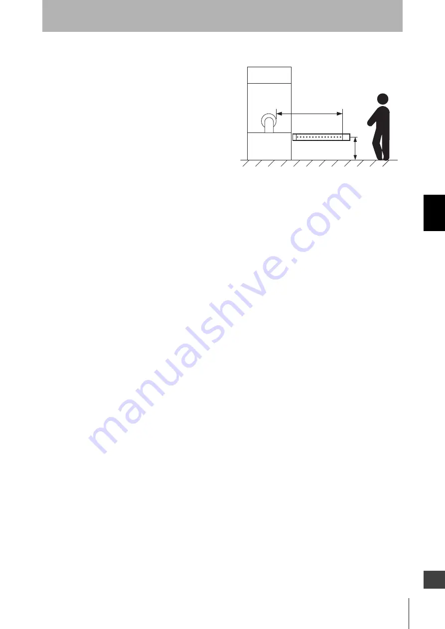
Detection Zone Parallel to Direction of Approach
Use K = 1,600 mm/s and C = (1200 - 0.4 x H) in
formula (1) for calculation. Note that C must not be
less than 850 mm.
S = 1,600 mm/s x (Tm + Ts) + 1200 - 0.4 x H
• S = Safety distance (mm)
• Tm = Machine's response time (s)
• Ts = Response time of F3SG-R from ON to OFF
(s)
• H = Installation height (mm)
Note that H must satisfy:
1000 ≥ H ≥ 15 (d - 50 mm) ≥ 0 mm
Also, you must include a hazardous condition under which a person may go through under a detection
zone if H exceeds 300 mm (200 mm for other purpose than industrial use) into risk assessment.
[Calculation example]
When Tm = 0.05 s, Ts = 0.008 s, and d = 14 mm:
S = 1,600 mm/s x (0.05 s + 0.008 s) + 1200 - 0.4 x 500 mm
= 1092.8 mm
4-1-2-2. Safety Distance Formulas according to ANSI B11.19
If a person approaches the detection zone of the F3SG-R orthogonally, calculate the safety distance as
shown below.
S = K x (Ts + Tc + Tr + Tbm) + Dpf
• S: Safety distance
• K: Approach speed to the detection zone (the value recommended by OSHA standard is 1,600 mm/
s)
Approach speed K is not specified in the ANSI B.11.19 standard. To determine the value of K to apply,
consider all factors, including the operator's physical ability.
• Ts = Machine's stopping time (s)
• Tr = Response time of the F3SG-R from ON to OFF (s)
• Tc = Machine control circuit's maximum response time required to activate its brake (s)
• Tbm = Additional time (s)
If a machine has a brake monitor, "Tbm= Brake monitor setting time - (Ts + Tc)". If it has no brake
monitor, we recommend using 20% or more of (Ts + Tc) as additional time.
• Dpf = Additional distance
According to ANSI's formula, Dpf is calculated as shown below:
Dpf = 3.4 x (d - 7.0): Where d is the detection capability (or object resolution) of the F3SG-R (unit: mm)
[Calculation example]
When K = 1,600 mm/s, Ts + Tc = 0.06 s, brake monitor setting time = 0.1 s,
Tr = 0.008 s, and d = 25 mm:
Tbm = 0.1 - 0.06 = 0.04 s
Dpf = 3.4 x (25 - 7.0) = 61.2 mm
S = 1,600 x (0.06 + 0.008 + 0.04) + 61.2 = 234 mm
+
Safety distance (S)
Hazard
Содержание F3SG-R Series
Страница 19: ...xvii F3SG 4RA 25 02TS User s Manual Introduction E 7 4 Revision History 107...
Страница 20: ...xviii Introduction F3SG 4RA 25 02TS User s Manual...
Страница 52: ...32 Chapter 3 End Cap F3SG 4RA 25 02TS User s Manual Setting with Rotary Switch and End Cap...
Страница 106: ...86 Chapter 5 Connectable Safety Control Units F3SG 4RA 25 02TS User s Manual Input Output Circuit and Applications...
Страница 112: ...92 Chapter 6 Maintenance Checklists F3SG 4RA 25 02TS User s Manual Checklists...


