Chapter 3: Robot Installation
ESTOPSRC
24 VS
5 VD
D
SYSPWRLT
7
6
5
4
2
3
1
17
16
8
10
9
11
12
13
14
15
XFP
15PDSUBM
MANUALSRC1
HIPWRREQ
MANUALRLY2
MANUALRLY1
HIPWRLT
ESTOPFP2
ESTOPFP1
HPLT5V
NC
MANUALSRC2
MANUALSRC1
SW1
MANUALRLY2
MANUALRLY1
MANUALSRC2
24 VS
SWL1
HIPWRREQ
HPLT5 V
HIPWRLT
D
ESTOPSRC
SW2
ESTOPFP2
ESTOPFP1
5 VD
D
2-PIN_MINI
SYSPWRLT
A
B
C
D
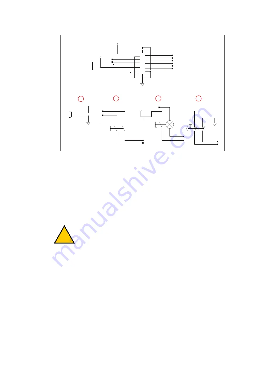
Figure 3-6. Front Panel Schematic showing the System Power LED (A), Manual/Auto Switch (B), High
Power On/Off (C), and Emergency Stop (D) circuits
IMPORTANT:
Disabling the High Power button violates IEC 60204-1. We
strongly recommend that you not alter the use of the High Power button.
3.5 Installing User-Supplied Safety Equipment
You are responsible for properly installing safety equipment to protect personnel from unin-
tentionally coming in contact with the robot. Depending on the design of the workcell, you can
use safety gates, light curtains, emergency stop devices, and other safety equipment to create a
safe environment.
!
WARNING:
Installing, commissioning, or operation of any robot without
adequate safety equipment is strictly prohibited. This equipment must be com-
pliant with all applicable and local standards. Failure to install suitable safety
equipment could result in injury or death.
Additional Information
: Refer to the
Robot Safety Guide (Cat. No. I590)
for more
information.
The user-supplied safety and power-control equipment connects to the system through the
XUSR and XFP connectors on the XSYSTEM cable. The XUSR connector (25-pin) and XFP (15-
pin) connector are both female D-sub connectors. Refer to the following sections for safety
equipment connection details.
Contacts on XUSR Connector
Use the information in the following table to understand the signals provided on the XUSR
connector.
24402-000 Rev B
eCobra 600 and 800 Robots with EtherCAT
49


