144
Functions Compatible with Servo Drivers with Absolute Encoders
Section 7-8
5.
When the mode where the data on the number of rotations is output only
in the + direction is set in the absolute encoder multi-turn limit setting, the
data received by the unit is handled as described below according to the
setting of "high-speed counter 1 operating mode" in the unit setup area:
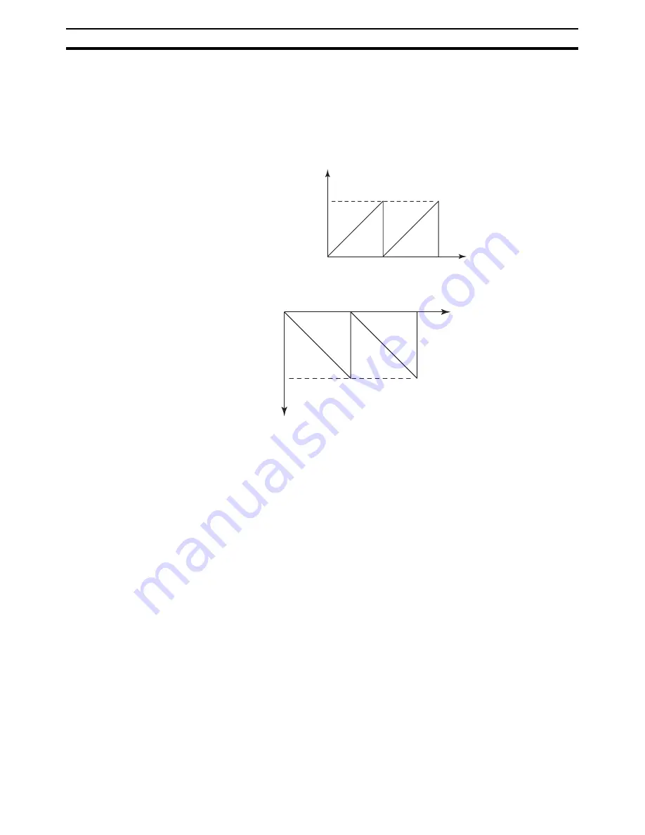
Ex) When a value between 0 and 65,534 is set on the servo driver
High-speed counter 1 operating mode (DM6605)": ABS linear (CW
-
)
mode
"High-speed counter 1 operating mode (DM 6605)": ABS linear (CW+)
mode
7-8-4
Counting Mode
Counting Operation
The counting operations by the ABS linear (CW
-
), ABS linear (CW+), and
ABS ring modes inherits the ones by the linear/ring modes of the pulse input
function on the models CS1W-HCP22(-V1)/HCA22(-V1). However, the normal
linear mode does not have the function to receive the data on the number of
rotations held in a servo driver with an absolute encoder.
Details of Each Counting
Mode
The details of the ABS linear (CW
-
), ABS linear (CW+), and ABS ring modes
are as follows:
■
ABS Linear (CW
-
) Mode (DM 6605 Bit 12 to 15: 2 Hex)
The pulse information when an absolute encoder is in reverse rotation is
counted with linear mode.
■
ABS Linear (CW+) Mode (DM 6605 Bit 12 to 15: 4 Hex)
The pulse information when an absolute encoder is in forward rotation is
counted with linear mode.
■
ABS Ring Mode (DM 6605 Bit 12 to 15: 3 Hex)
The pulse information of an absolute encoder is counted with ring mode.
(Only the initial incremental pulse (angle) at reading an absolute value is used
as the absolute value.)
7-8-5
ABS Number of Rotations Present Value (AR 04 to 05)
The multi-turn data (a present value read from an encoder) is input to the unit
after the SEN signal is input to a servo driver. The data is stored as the ABS
0
Present value
ABS Present Value is positive value.
0
Present value
ABS Present Value is negative value.
Содержание CS1W-HCA12-V1
Страница 2: ......
Страница 6: ...vi...
Страница 20: ...xx Conformance to EC Directives 7...
Страница 38: ...18 Models and System Configurations Section 1 2...
Страница 78: ...58 Fail safe Circuits Section 3 5...
Страница 138: ...118 AR Area Section 6 4...
Страница 204: ...184 Improved Instructions Section 7 14...
Страница 222: ...202 Cycle Time Section 8 3...
Страница 240: ...220 Troubleshooting Flowcharts Section 9 5...
Страница 244: ...224 Precautions when Using the CX Programmer Appendix A...
Страница 252: ......
Страница 253: ......


