Connecting J1708 /J1587
Vehicle Data Bus Connections
11-12
MAY CONTAIN U.S. AND INTERNATIONAL EXPORT CONTROLLED INFORMATION
80-J4866-2 Rev. G
Connecting J1708 /J1587
1.
Start the vehicle and verify that the truck is in good working order and displays no dash
faults.
2.
Verify that the engine ignition switch is OFF.
3.
Locate the engine data diagnostic connector.
• The data source wires to the engine data diagnostic connector are a twisted pair that
should remain twisted after the installation is complete.
• Consult the manufacturer’s wiring diagrams to identify the wires (some are marked
DATA+ and DATA- or D/L+ and D/L-, and some are marked with numbers or colors).
• Note which wire is plus (+) and which is minus (-).
• To avoid confusion, cut and splice the positive wires first and then the negative wires.
Because there usually is not much slack in the engine data diagnostic connector
wires, be careful in cutting and splicing to them.
4.
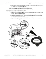
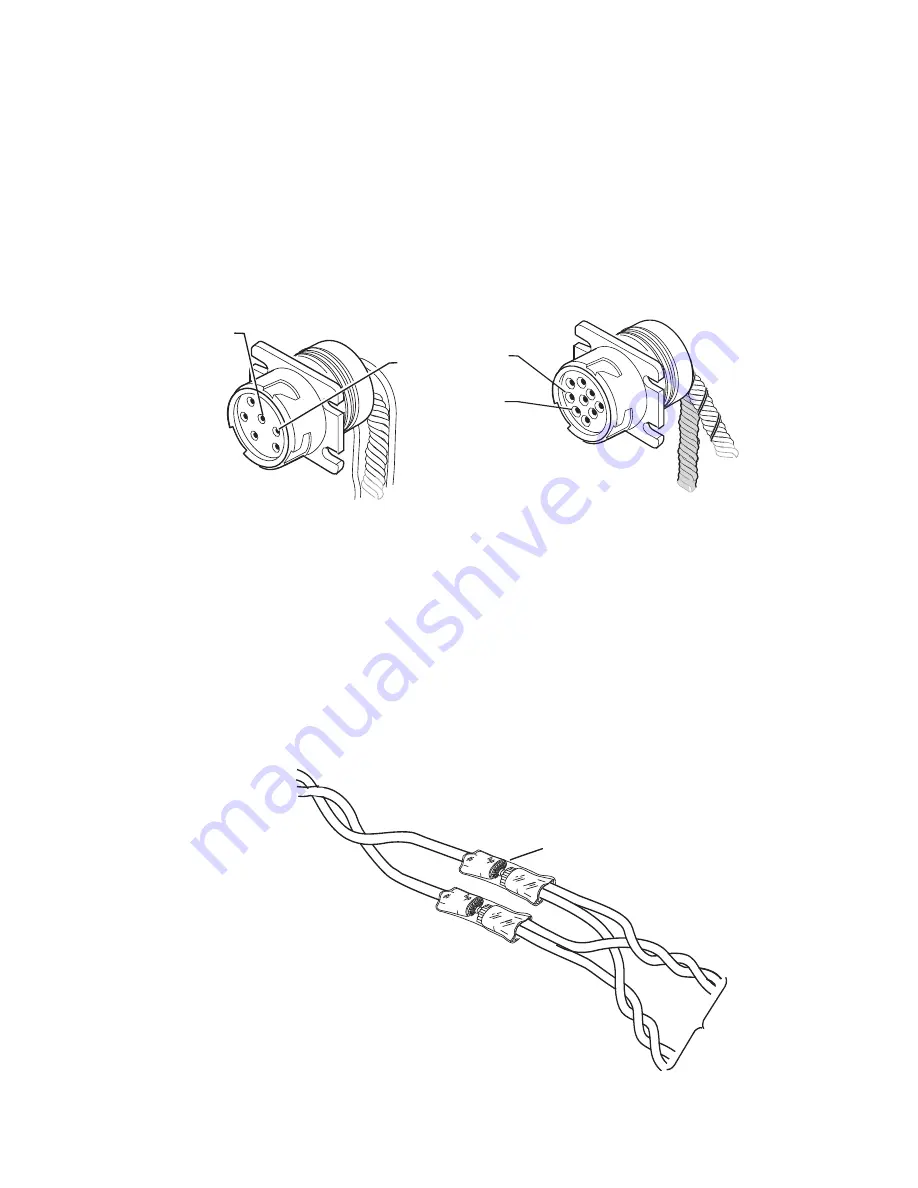
Splice the brown J1708+ wire from the accessory cable to the DATA+ (pin F) wire of the
engine diagnostic connector. Reconnect the wires.
Pin A
J1708/J1587
DATA LINK+
Pin B
J1708/J1587
DATA LINK-
6-Pin Diagnostic Connector
08AAA_051A
Pin F
J1587+
Pin G
J1587-
9-Pin Diagnostic Connector
MCP100
Accessory Cable
Butt Splice
Data Link-
Data Link-
Data Link+
Data Link+
To vehicle
datalink
J1708-
J1708+
Содержание MCP100
Страница 1: ...MCP100 Installation Guide 80 J4866 2 Rev G October 2015 ...
Страница 12: ...xii MAY CONTAIN U S AND INTERNATIONAL EXPORT CONTROLLED INFORMATION 80 J4866 2 Rev G ...
Страница 224: ...Standard RMA Procedure C 2 MAY CONTAIN U S AND INTERNATIONAL EXPORT CONTROLLED INFORMATION 80 J4866 2 Rev G ...
Страница 250: ...Documentation Format Feedback Form G 4 MAY CONTAIN U S AND INTERNATIONAL EXPORT CONTROLLED INFORMATION 80 J4866 2 Rev G ...


