background image

8 | 

P a g e


4


SYNC Configuration 

Layer N Smart Probe products are easily configurable through SYNC configuration software. Ensure SYNC is running on your 

Windows OS computer before continuing. Connect your SP-010 to your computer through your Layer N Smart Interface.  

Note: 

SYNC is available to download for free on the OMEGA website.


4.1


Connecting to SYNC - Automatic Detect 

Once the SP-010 and Layer N Smart Interface are connected to your computer, SYNC will automatically detect it and begin 

displaying readings. 

Note:

 If you have successfully connected your SP-010 to SYNC and have readings appearing in SYNC, skip ahead to 

the section titled Load Cell Interface.


4.2


Connecting to SYNC – Manual 

If SYNC does not automatically detect your device, follow these instructions to manually connect it. 


Step 1: 

Click on the 

  icon located on the top left of the SYNC interface. 


Step 2: 

Proceed through the Add Device Wizard and click 

End Device / Probe

.


4.2.1


Communication Interface 

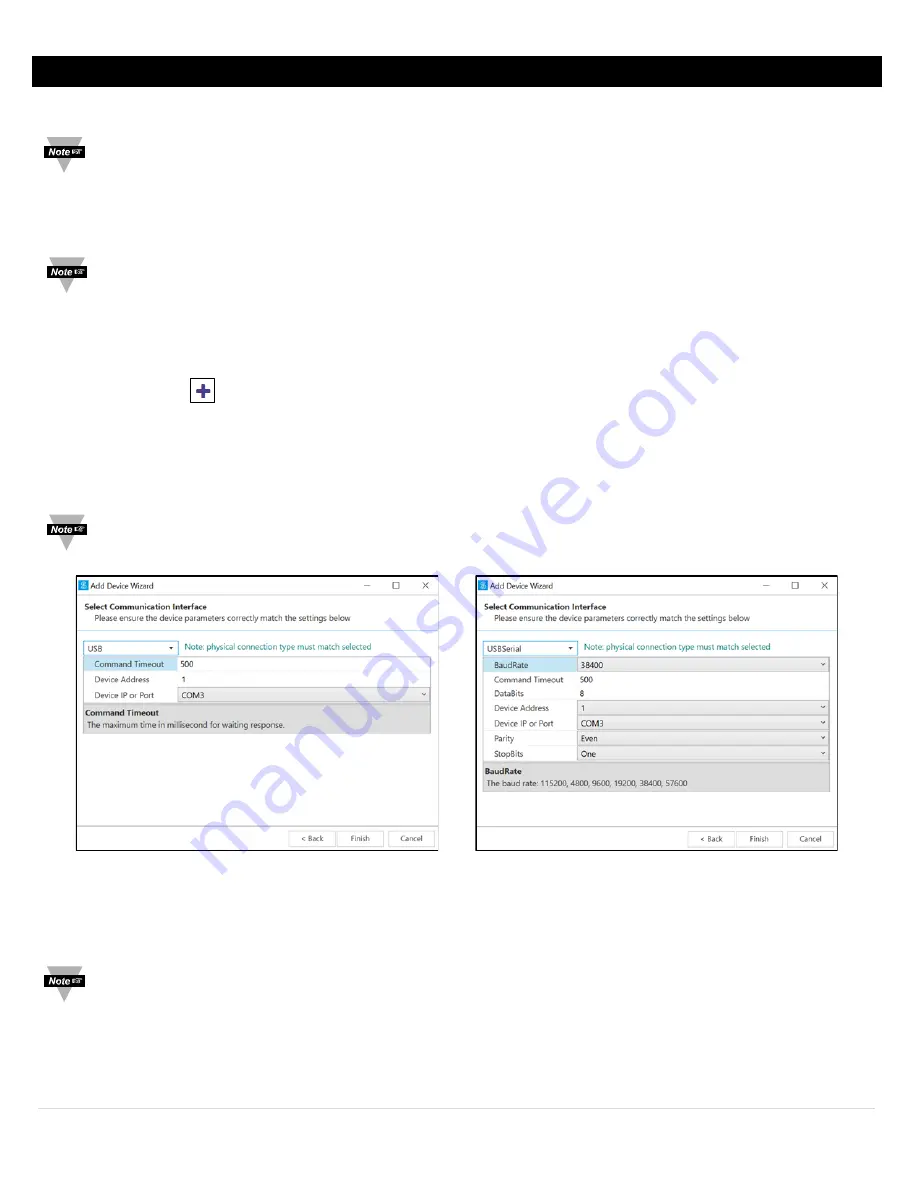
Set the communication parameters for the Layer N Smart Interface that you are connecting. 

Note: 

The connection type and parameters must be accurate for a proper connection to be established. Failure to 

accurately setup communication parameters may result in communication errors.


• 

Connection Type: 

Select the type of connection you have between your SP-010 and your computer.  

• 

Command Timeout: 

The maximum time (in milliseconds) for a command to be completed before the command is 

aborted. 

Note: 

The default command timeout is 500 milliseconds. It is recommended that this section be left alone to avoid 

communication errors. 


USB Communication Interface 

USB Serial Communication Interface 

Содержание SP-010

Страница 1: ...1 P a g e TM User sGuide Shop online at omega com e mail info omega com For latest product manuals www omegamanual info SP 010 Load Cell Smart Probe ...

Страница 2: ...only Customer Service 1 800 622 2378 USA Canada only Engineering Service 1 800 872 9436 USA Canada only U S A Headquarters Tel 203 359 1660 e mail info omega com Fax 203 359 7700 The information contained in this document is believed to be correct but OMEGA accepts no liability for any errors it contains and reserves the right to alter specifications without notice ...

Страница 3: ...teable 12 5 1 2 4 Smart Sensor 12 5 1 3 Load Cell Configuration 12 5 1 3 1 Apply Scaling 12 5 1 3 2 Lock 12 5 1 3 3 Assigned 12 5 1 3 4 Available 12 5 1 4 Load Cell Device Byte 12 5 1 5 Load Cell Parameters 13 5 1 5 1 Sensitivity 13 5 1 5 2 Range 13 5 1 5 3 Impedance 13 5 1 5 4 TARE 13 5 1 6 Load Cell User Calibration Parameters 14 5 1 7 Load Cell IPSO Definition 14 5 1 7 1 Sensor Trigger Function...

Страница 4: ...4 P a g e 5 2 4 1 Sensor Trigger Function 17 5 2 5 DIO Input Circuitry 17 5 3 Outputs 18 5 3 1 PWM Rate 18 5 3 2 Active State 18 5 3 3 Output Drive 18 5 3 4 Output Type 18 6 Specifications 19 ...

Страница 5: ...evice as it contains important information relating to safety and EMC Failure to follow all the safety precautions may result in injury and or damage to your equipment The following labels identify information that is especially important to note Note Provides you with information that is important to successfully setup and use the SP 010 Caution or Warning Tells you about the risk of electrical s...

Страница 6: ...g effects and allow for battery powered operation The SYNC software also allows customizing the sensitivity of the bridge in mV V and the maximum range of the bridge in the specific units of measure The default unit of measure is kg and can also be customized TARE and 2 Point Linearization are also available through SYNC The Layer N SP 010 features 2 configurable digital I O pins These can be used...

Страница 7: ...M12 4 pin connector Use the M12 4 Pin Connector diagram below to connect your bridge sensor to your SP 010 Pin Name Function Pin 1 DIO 0 Discrete I O Signal 0 Pin 2 INTR Interrupt Signal Pin 3 SCL I2C Clock Signal Pin 4 SDA I2C Data Signal Pin 5 Shield Shield Ground Pin 6 DIO 1 Discrete I O Signal 1 Pin 7 GND Power Ground Pin 8 3 3VDD Power Supply Pin Name Function Pin 1 Exc Excitation Return Pin ...

Страница 8: ...y detect your device follow these instructions to manually connect it Step 1 Click on the icon located on the top left of the SYNC interface Step 2 Proceed through the Add Device Wizard and click End Device Probe 4 2 1 Communication Interface Set the communication parameters for the Layer N Smart Interface that you are connecting Note The connection type and parameters must be accurate for a prope...

Страница 9: ...value based on all the other bits in the character StopBits The number of bits used to indicate the end of the character Once you have completed setting the communication parameters for your device click Finish 4 3 Load Cell Interface The SP 010 measures the bridge voltage to determine the applied force using bridge characteristics provided by the user To configure the settings on your SP 010 foll...

Страница 10: ...ctual Box Step 3 Place your high reference and click Capture next to High Reading This will capture the measurement for the high reference in the high reading box Enter your high reference weight in the High Actual Box Step 4 Click Calibrate to save your calibration Note Clicking Calibrate or Clear Calibration will clear the TARE offset 4 4 Setting Alarms Alarms are set by clicking the icon in SYN...

Страница 11: ...mation When powered on or after a device reset each Smart Sensor based device will enumerate 1 or more sensor instances which are described by the device specific Sensor Descriptors which include configuration options measurement type and units of measure for the corresponding sensor values Additional sensor information is provided in sensor specific IPSO object descriptions which include extended...

Страница 12: ...ll Configuration 7 6 5 4 3 2 1 0 Available Assigned Apply Scaling Lock Sensor Type Range Not Used 0 5 1 3 1 Apply Scaling If set the user defined Offset and Gain values will be used to adjust the sensor reading Result Raw Reading Gain Offset 5 1 3 2 Lock If set the user specified units of measure string 4 character maximum will be used in place of the default units of measure 5 1 3 3 Assigned Refe...

Страница 13: ...e provided in kilogram kg When entering the full scale range it is recommended that the value is converted to kg An alternative is to change the units of measure enter appropriate scale factors and set the lock bit in the sensor descriptor field Typical load cells also specify a maximum overload value The SP 010 will set the maximum measurement value to 150 of the specified range 5 1 5 3 Impedance...

Страница 14: ... where X actual applied load and Y represents the reading captured by the device after the calibration process User Calibration Parameter Name Range Factory Reset Description 0 Low Reading X1 100000 0 0 Value read by SP010 lower value 1 Low Actual Y1 100000 0 0 Actual applied load lower value 2 High Reading X2 100000 Full Scale Value read by SP010 higher value 3 High Actual Y2 100000 Full Scale Ac...

Страница 15: ...ardwired to the Digital outputs These may be used to detect the state of external switches output off or to monitor the state of the outputs The DIO Input descriptor is at base addresses 0x0068 5 2 1 DIO Descriptor Offset Name Value Description 0x00 Sensor Type 0x18 Digital Type Bit mapped 0x01 Data Type Format 0x46 Configurable Float type 0x02 Configuration 0x23 Scaling applied Bits 0 and 1 enabl...

Страница 16: ... Device Interface documentation for further information 5 2 2 4 Available The Available bit will always read as 0 Refer to the Smart Sensor Device Interface documentation for further information 5 2 3 DIO Device Configuration The DIO Device Configuration allows enabling each of the 2 input bits and selecting whether the input is active HIGH or active LOW If the Invert Bit is set the signal will be...

Страница 17: ... The internal processor drives the Output Control signal to turn on the output driver which will force the output LOW When the state of the DIO input signal is to be read the processor applies 3 0 VDC to the Input Bias signal and reads the level detected at the Input Sense If the output is inactive an external signal may be used to force the input level LOW A diode provides protection of external ...

Страница 18: ...1 10 Hz PWM signal has constant 10 Hertz frequency 100 msec repetition rate with 0 100 duty cycle 2 1 Hz PWM signal has constant 1 Hertz frequency 1 second repetition rate with 0 100 duty cycle 3 0 1 Hz PWM signal has constant 0 1 Hertz frequency 10 second repetition rate with 0 100 duty cycle 5 3 2 Active State The SP 010 probe outputs may be configured as Active HIGH or Active LOW When set to 1 ...

Страница 19: ...MAX 30 VDC ACCURACY Linearity Error 0 03 FSO 25 C Thermal Error 0 005 FSO C ENVIRONMENTAL Operating Temperature 40 to 85 C 40 to 185 F Rating IP67 when mated MECHANICAL Dimensions 22 1 mm W x 96 7 mm L 0 87 x 3 80 not including mounting tabs GENERAL Agency Approvals CE EMC 2014 30 EU LVD 2014 35 EU Compatibility Compatible with OEG SYNC configuration software Layer N Cloud and Modbus Networks ...

Страница 20: ...GA if the unit is found to be defective it will be repaired or replaced at no charge OMEGA s WARRANTY does not apply to defects resulting from any action of the purchaser including but not limited to mishandling improper interfacing operation outside of design limits improper repair or unauthorized modification This WARRANTY is VOID if the unit shows evidence of having been tampered with or shows ...

Страница 21: ...rs M U Turbine Paddlewheel Systems M U Totalizers Batch Controllers pH CONDUCTIVITY M U pH Electrodes Testers Accessories M U Benchtop Laboratory Meters M U Controllers Calibrators Simulators Pumps M U Industrial pH Conductivity Equipment DATA ACQUISITION M U Communications Based Acquisition Systems M U Data Logging Systems M U Wireless Sensors Transmitters Receivers M U Signal Conditioners M U Da...

Отзывы: