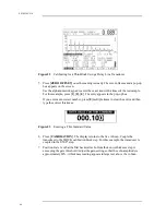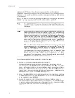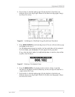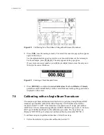
Calibrating the EPOCH 4PLUS
Part # 910-250C
59
7.3
Calibrating with a Delay Line Transducer
The sample delay line calibration described below is performed using Olympus NDT
transducer part number V202-RM, with a frequency of 10.0 MHz and an element
diameter of 0.25" (6 mm). The calibration requires a test block with two known
thicknesses, made from the material to be measured. Ideally, the two thicknesses
measurements are both below and above the expected thickness of the material to be
inspected.
For this example, we are using Olympus NDT standard 5-step steel test block part number
2214E. The steps measure 0.100", 0.200", 0.300", 0.400", and 0.500".
Note:
If the EPOCH 4PLUS is set to work in metric units, the calibration process is
exactly the same, except that the entries below will be in millimeters, rather
than inches.
To calibrate using a Delay Line transducer, follow these steps:
1. Follow the initial set-up procedure outlined in Section 7.2.
Connect the transducer to an appropriate cable and then connect the cable to either of
the transducer posts on the EPOCH 4PLUS. With a Zero Offset of 0.000 µs, the Main
Bang (or excitation pulse) should appear on the left side of the screen.
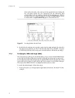
Increase the Zero Offset until the Main Bang moves off the left side of the screen and
the interface echo from the end of the delay line tip appears on the screen.
Verify that the echo represents the end of the delay by tapping your finger on the end
of the couplant-coated delay line. This dampens the signal and the echo should jump
up and down on the screen. Use the Zero Offset to move this echo to the left side of the
screen so that it is barely visible.
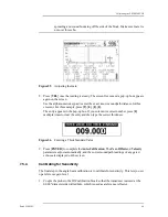
2. Press [CALIBRATION]. A Cal symbol will appear to the right of the A-Scan,
signifying the EPOCH 4PLUS is in the Auto-Calibration mode. To exit the Auto-
Calibration mode at any point, press [ENTER].
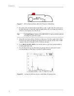
3. Couple the transducer to the THIN calibration block step. For this example, the
transducer will be coupled to the 0.100" step.
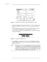
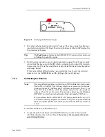
4. Position Gate 1 so that the first backwall echo from the known thickness step is
exceeding the gate threshold. Adjust the gain setting so that the echo amplitude is
approximately 80%. A thickness reading appears in large text above the A-Scan.
Note:
Make sure it is the first backwall echo being gated, not a multiple echo from
the end of the delay line tip.
Содержание Panametrics Epoch 4 Plus
Страница 4: ...EPOCH 4PLUS...
Страница 10: ...EPOCH 4Plus...
Страница 18: ...8 EPOCH 4PLUS...
Страница 40: ...30 EPOCH 4PLUS...
Страница 50: ...40 EPOCH 4PLUS...
Страница 54: ...44 EPOCH 4PLUS...
Страница 92: ...82 EPOCH 4PLUS...
Страница 172: ...162 EPOCH 4PLUS...
Страница 184: ...174 EPOCH 4PLUS Figure D 3 VGA Adapter Cable Olympus NDT Part EP4 C 15VGA 6 Figure D 4 VGA Adapter Cable Wire Run List...

