Using the Gates
Part # 910-250C
47
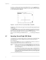
While in Edge Depth mode, thickness readings are made to the leading edge of the
first signal to exceed the flaw gate level. In Peak Depth mode, thickness readings are
made to the peak of the highest amplitude signal that falls within the gate.
If no refracted angle is entered, a Minimum Depth value appears above the display.
This value refers to the minimum detected thickness value and is only updated if a
lower value is measured. To reset the minimum depth value, press either [GATE 1] or
[GATE 2].
Note:
To obtain the most accurate and consistent thickness or soundpath readings,
select the Peak Depth mode. The apparent arrival time of the leading edge of
a signal varies with the signal’s amplitude. As a result, the instrument gain
setting, coupling conditions, and any other factor affecting signal amplitude,
has an impact on the accuracy of a reading made in the edge depth mode. The
effects of these factors are not completely eliminated in the peak depth
mode, but they are greatly reduced. If Peak Depth is selected, perform
calibrations using the peak of the signal. However, when using a dual
transducer, due to the jagged peaks, we recommend you use Edge Depth.
6.4
Taking Echo-to-Echo Thickness Readings
The EPOCH 4PLUS is also equipped to make measurements between successive echoes.
Measurements can be made between two consecutive backwall echoes or between an
interface echo and any other selected signal. This provides the capability to measure
thickness through coatings or to do low speed immersion testing. A second gate (Gate 2)
is used to capture data from the second back wall echo. Echo-to-Echo readings are made
by calculating the separation between the detected echoes in Gate 1 and Gate 2.
Echo-to-Echo thickness readings cannot be made in the unrectified RF display mode.
Calibrate the EPOCH 4PLUS (see Section 7 – Calibrating the EPOCH 4PLUS) and follow
these steps to make Echo-to-Echo thickness readings:
1. Position Gate 1 over the region where the first back echo is expected to appear.
2. Press [2
nd
F], [DEPTH/%AMP] (ECHO-ECHO) to activate the Echo-to-Echo
measurement mode. The following information appears in the function boxes at the
bottom of the display:
F1 = EDGE, F2 = PEAK
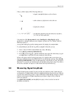
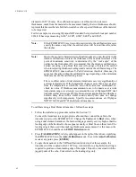
3. Select either edge-to-edge or peak-to peak. The icon
appears for peak-to-peak
or
appears for edge-to-edge to the right of the display to indicate Echo-to-
Echo measurements are being used. If Gate 2 is off and the Echo-to-Echo mode is
turned on, then Gate 2 is automatically turned on.
4. Define the Blanking Period to avoid possible false readings that could occur due to
transducer ringing or material noise. A dead zone or blanking period is necessary after
the detection of the first echo. This period is defined during set-up as the separation
between the start of Gate 1 and the start of Gate 2. When an echo is detected in Gate 1,
the Gate 2 start automatically adjusts to trail the detected echo by the blank period.
Содержание Panametrics Epoch 4 Plus
Страница 4: ...EPOCH 4PLUS...
Страница 10: ...EPOCH 4Plus...
Страница 18: ...8 EPOCH 4PLUS...
Страница 40: ...30 EPOCH 4PLUS...
Страница 50: ...40 EPOCH 4PLUS...
Страница 54: ...44 EPOCH 4PLUS...
Страница 92: ...82 EPOCH 4PLUS...
Страница 172: ...162 EPOCH 4PLUS...
Страница 184: ...174 EPOCH 4PLUS Figure D 3 VGA Adapter Cable Olympus NDT Part EP4 C 15VGA 6 Figure D 4 VGA Adapter Cable Wire Run List...

