background image

Using Software Options

Part # 910-250C

143

9.15

AUTO-FREEZE

This software option allows you to make the instrument freeze for a specified period of 
time when a signal breaks a gate on the EPOCH 4PLUS display.

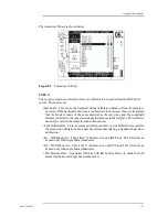
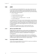
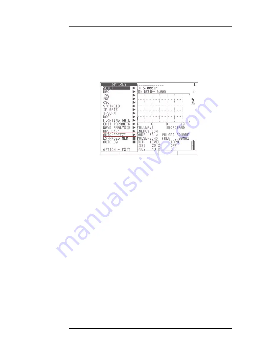
This option is listed in the Options Menu as shown below. 

Figure 95

Options Menu

This option functions with the following options:

DAC

TVG

Advanced DAC/TVG

PRF

CSC

Spotweld OVERLAY

Spotweld ASSISTANT

INTERFACE GATE

The Auto-Freeze option is activated in the Options Menu using an activation box. Press 
[ENTER] on AUTO-FREEZE as shown below:

Содержание Panametrics Epoch 4 Plus

Страница 1: ...EPOCH 4PLUS Part No 910 250C USER S MANUAL Advanced Test Equipment Rentals www atecorp com 800 404 ATEC 2832 Established 1981...

Страница 2: ...by Olympus NDT Inc All rights reserved No part of this manual may be reproduced or transmitted in any form or by any means electronic or mechanical including photocopying recording or by any informati...

Страница 3: ...warranty does not include transducers transducer cables or battery The customer will pay shipping expense to the Olympus NDT plant for warranty repair Olympus NDT will pay for the return of the repair...

Страница 4: ...EPOCH 4PLUS...

Страница 5: ...y 6 2 6 Using a AA Alkaline Battery 7 3 Managing Basic Operations 9 3 1 Powering up LCD Screen Adjustment 9 3 2 Using the Keypad 10 3 2 1 Enter Key 10 3 2 2 Direct Access Operation 10 3 3 Summarizing...

Страница 6: ...Type Selection 38 4 4 7 Pulser Frequency Selection 39 5 Managing Special Waveform Functions 41 5 1 Reject 41 5 2 Peak Memory 41 5 3 Peak Hold 42 5 4 Screen Freeze 42 6 Using the Gates 45 6 1 Position...

Страница 7: ...Readings 75 8 6 Incrementing ID Codes 76 8 7 Recalling Transducer Calibrations and Waveforms 77 8 8 Saving and Recalling Quick Recall Calibrations 78 8 9 Creating Memos 78 8 10 Editing a File 79 9 Us...

Страница 8: ...CH 4PLUS Datalogger 117 9 9 Interface Gate 121 9 9 1 Activating the Interface Gate 122 9 9 2 Operating in Standard Mode 122 9 9 3 Operating in Echo to Echo Mode 122 9 9 4 Managing Gate Positioning and...

Страница 9: ...A and C Values 148 9 17 API 5UE 149 9 17 1 Description 149 9 17 2 API 5UE and the EPOCH 4PLUS 150 9 17 3 Activating the API 5UE Software 151 9 17 4 Calibrating to a Reference Standard 152 9 17 5 Crac...

Страница 10: ...EPOCH 4Plus...

Страница 11: ...dy memo feature allows unlimited comment and data description entries A memory display screen makes it possible to review the contents of any file by scrolling through the actual data prior to deletin...

Страница 12: ...tions using the gates calibrating the EPOCH 4PLUS managing the datalogger and data communication features and using software options 1 3 Audience This document is intended for any operator using the E...

Страница 13: ...ications Contact us at pana OlympusNDT com In all your correspondence please include the title of the document its part number release date and the specific section upon which you are commenting Conve...

Страница 14: ...is document In addition the document number is also changed to reflect the revision The table below shows a list of all revisions for this document 1 7 Technical Help Call Olympus NDT and ask for a sa...

Страница 15: ...ower cable from the Charger Adapter unit to the Charger AC Adapter input jack on the right side of the EPOCH 4PLUS 3 Turn the EPOCH 4PLUS on via the front keypad 4 Proceed with normal operation 2 2 Us...

Страница 16: ...O CHARGE ANY OTHER BATTERIES Doing so may cause an explosion and injury Do not attempt to charge other electronic equipment This will cause permanent damage To replace the battery follow these steps 1...

Страница 17: ...ot in use Whenever possible the battery should remain connected to the EP4 MCA Charger Adapter overnight or over a weekend so that it achieves 100 of full charge The battery must reach full charge on...

Страница 18: ...8 EPOCH 4PLUS...

Страница 19: ...therwise press ENTER to continue Use the slewing keys to move the highlight bar over the desired selection Parameters Resets the unit s parameters to the factory settings Database Erases the EPOCH 4PL...

Страница 20: ...or key to change an activated parameter value Pressthe ENTER keymultipletimestotogglethroughtheinstrumentsettings Tomove quickly through the sequence press ENTER multiple times in succession or simply...

Страница 21: ...d which resembles a telephone keypad is used exclusively for datalogging purposes The left side of the keypad contains the primary operating keys of the EPOCH 4PLUS Most parameters on the EPOCH 4PLUS...

Страница 22: ...national Keypad 3 3 1 Main Keypad Functions English Int l Color Function Blue Sensitivity Adjusts system sensitivity COLOR COLOR White Option Accesses the instrument s setup menu and software options...

Страница 23: ...g Saves displayed thickness reading in current file If the EPOCH 4PLUS is in Time of Flight mode the value will be in microseconds Purple Save Waveform Saves the current waveform and instrument setup...

Страница 24: ...r parameter White Orange Filter Moves directly to filter parameters Orange Peak Memory Function Activates the Peak Memory function allowing continuous accumulation of peak envelope data with the live...

Страница 25: ...US Auto Calibration feature in conjunction with the ZERO OFFSET and VELOCITY keys White Yellow BRIGHTNESS Adjustment Adjusts the brightness of the Liquid Crystal Display LCD English Int l Color Functi...

Страница 26: ...ough Z the entry of symbols above the ID key and the Delete function above the 1 key Yellow Number Entry Allows entry of the number keys 0 through 9 Blue ID Entry Allows entry of an ID Identifier loca...

Страница 27: ...ot be adjusted Also parameters that are limited by hardware and or software constraints such as Damping cannot be adjusted To activate the Editable Parameters menu follow these steps 1 Press the OPTIO...

Страница 28: ...he Editable Parameters screen opens Figure 4 Viewing the Editable Parameters Screen 4 Press the ENTER key to move downward to different parameters 5 Use the left and right slewing keys to select which...

Страница 29: ...meters to savethesettings and return to the Options menu When you select one of the parameters that you edited the new preset values appear above the F keys Figure 6 Viewing New Preset Values 3 5 Colo...

Страница 30: ...djust the color of the display 3 6 Managing the Display The EPOCH 4PLUS can present theA Scan in two different display formats splitscreen and full screen A split screen presents simultaneous viewing...

Страница 31: ...esets press 2nd F then ZERO OFFSET DIV On the right side of the waveform display a set of display flags and markers appears when certain functions are active Bottom of the screen Displays the preset v...

Страница 32: ...ng for you to press one of the second function keys Press 2nd F again to cancel Indicates the EPOCH 4PLUS is in the Peak Depth mode thickness and soundpath measurements are made to the peak of the hig...

Страница 33: ...ates Curved Surface Correction is active SW Indicates Spotweld Overlay is active SWA Indicates Spotweld Assistant is active IF Indicates Interface Gate is active WV Indicates Wave Analysis is active A...

Страница 34: ...CH 4PLUS follow these steps 1 Move the highlight bar over the Language option and press ENTER 2 Move the highlighted bar over the desired language and press ENTER 3 Press OPTION to exit 3 7 2 Units of...

Страница 35: ...analog digital converter card The information is outputted as a voltage either on a 0 1 volt or 0 10 volt scale Select the output scale and then connect the EPOCH 4PLUS to the external device via the...

Страница 36: ...dge to the location at which the flaw is being detected This allows you to butt the end of a ruler up against the front of the wedge to find the surface distance to the detected flaw To activate the X...

Страница 37: ...cting both high and low pass filters individually Zero Offset The zero offset parameter compensates for the time offset between electric and acoustic zero points This offset is attributed to cable and...

Страница 38: ...ht bar over VGA On and press ENTER in the corresponding box signifies the VGA output is on 2 Press ENTER again to turn it off 3 Press OPTION again to the return to the live screen 3 7 8 Beep On When B...

Страница 39: ...light 3 7 12 Filled Peak When you select Filled Peak a waveform or echo envelope that is frozen on the screen whenusingeitherthePeakMemoryorPeakHoldfeatureappearsfilled in ratherthanas an outline trac...

Страница 40: ...30 EPOCH 4PLUS...

Страница 41: ...t corner 4 Adjust gain in 0 1 dB increments by pressing the or key 5 Holdthe or keytograduallyincreasetheslewingrate Totalsystemsensitivity is 110 0 dB 4 2 Using AUTO 80 AUTO 80 quickly adjusts the ga...

Страница 42: ...E 2 2 Press F4 to turn on the gate if necessary 3 Use the green slewing keys to position the gate over the desired echo Be sure theecho breaks the gate threshold 4 Press F5 The peak of the highest amp...

Страница 43: ...make adjustments in 6dB increments The cursor position is to the left of the decimal point 2 Use the and keys to increment or decrement 3 Press F1 to make adjustments in 0 1 dB increments The cursor p...

Страница 44: ...adjusted appears at the top left of the screen and directly above the waveform In the Split Screen mode the parameter is highlighted on the lower half of the EPOCH 4PLUS screen Note For reviewing the...

Страница 45: ...een 2 Use the function keys for direct access or the and keys to toggle among the four selections 4 4 3 Damping The damping control lets you optimize the waveform shape for high resolution measurement...

Страница 46: ...can use one of many narrowband filters Filters improve signal to noise ratio by filtering out unwanted low or high frequency noise outside the test frequency spectrum The EPOCH 4PLUS user interface fo...

Страница 47: ...ILTER to go directly to the filter selection 2 Use the function keys for direct access to the preset selection or use and keys to change the selection Advanced User Mode In the Advanced Usermode the f...

Страница 48: ...e Low and High Pass Filter settings follow these steps 1 Press PULSER multiple times until the desired filter selection is highlighted or press 2ND F PULSER FILTER to go directly to the filter selecti...

Страница 49: ...only when the EPOCH 4PLUS is in the Square Wave Pulser mode In Spike mode the selection is disabled To select Pulser Frequency Selection follow these steps 1 Press PULSER multiple times until the FREQ...

Страница 50: ...40 EPOCH 4PLUS...

Страница 51: ...hese steps 1 Press 2ndF VEL REJECT 2 Use the function keys to select preset values or use the and keys to adjust the reject level upward or downward Any signal whose amplitude is less than or equal to...

Страница 52: ...Similarities and or differences in the waveforms can be noted to help determine the unknown material s acceptability status Note The Peak Hold function cannot be activated in the unrectified RF displa...

Страница 53: ...ain thickness or soundpath data TheFreeze functiondiffers fromPeakMemoryinthat nonewdataisacquiredandadded to the instrument display The FREEZE key is ideal for high temperature measurements When Free...

Страница 54: ...44 EPOCH 4PLUS...

Страница 55: ...when using an angle beam transducer signal amplitude time of flight data or a trigger for minimum depth or threshold alarms Movement of Gate 1 is controlled via the red GATE 1 key To access the start...

Страница 56: ...lue and that the Gate 1 width exceeds the maximum expected value Note When used for thickness gaging Gate 1 level should be set just high enough to avoid false readings When used for flaw detection Ga...

Страница 57: ...all echoes or between an interface echo and any other selected signal This provides the capability to measure thickness through coatings or to do low speed immersion testing A second gate Gate 2 is us...

Страница 58: ...riodmay prevent false readings the minimum measurable thickness is limited to a value slightly greater than the blanking period Figure 12 Set up for Peak to Peak Measurement 6 5 Locating Flaws with an...

Страница 59: ...set up all soundpath data is treated as if the information is in the first leg When working beyond the first signal segment it is important that you enter an exact thickness of the material into the...

Страница 60: ..._____ indicating no reading was taken 6 7 Operating Time of Flight TOF Mode The EPOCH 4PLUS is capable of displaying Time of Flight TOF soundpath data for an echo that breaks the gate Time of Flight i...

Страница 61: ...e instrument at the current material velocity setting Zoom is especially useful in certain flaw detection applications For example when detecting branches of cracking such as inter granular stress cor...

Страница 62: ...ng F4 for ON 6 9 1 Threshold Alarms Threshold alarms can be set on Gate 1 and or Gate 2 To set a threshold alarm on Gate 1 follow these steps 1 Press GATE1 andusethestart width andlevelparameterstopos...

Страница 63: ...set on Gate 1 and or Gate 2 To set a minimum depth alarm on Gate 1 follow these steps 1 Press GATE1 andusethestart width andlevelparameterstopositionthegateover the desired area Be sure the gate start...

Страница 64: ...EPTH AMP ECHO ECHO to activate the Echo to Echo Measurement mode 3 Press 2nd F GATE 2 ALARM 2 to activate the alarm 4 Press F3 to select the minimum depth alarm 5 Use the and keys to set the desired m...

Страница 65: ...Auto Calibration feature when the EPOCH 4PLUS is in the following modes Microsecond Time Of Flight Mode DAC TVG Topics are as follows Getting Started Calibrating with a Straight Beam Transducer Calibr...

Страница 66: ...ith the function keys or the and keys Note Refer to Chapter 4 Adjusting the Pulser Receiver for information on how to set the pulser and filter parameters 7 2 Calibrating with a Straight Beam Transduc...

Страница 67: ...e text above the A Scan Once a steady reading is achieved press ZERO OFFSET The screen freezes and a pop up box appears on the screen Use the alphanumeric keypad to enter the exact known thickness of...

Страница 68: ...ype the correct thickness Figure 21 Entering a Thick Standard Value 9 Press ENTER to complete the Auto Calibration The Zero Offset and Velocity parameters adjust automatically and the correct thicknes...

Страница 69: ...POCH 4PLUS With a Zero Offset of 0 000 s the Main Bang or excitation pulse should appear on the left side of the screen Increase the Zero Offset until the Main Bang moves off the left side of the scre...

Страница 70: ...correct number press 0 multiple times to clear the entry and then type the correct thickness Figure 23 Entering a Thin Standard Value 6 Press CALIBRATION The display returns to the live A Scan Couple...

Страница 71: ...Zero Offset and Velocity parametersadjustautomatically andthecorrectthicknessreadingofanygatedechois displayed on the screen Note It is possible to use Auto Calibration on a single test block of known...

Страница 72: ...a few degrees from the temperature at which the zero offset value was established re check its value If thickness measurements are to be made over a wide temperature range we strongly recommend the u...

Страница 73: ...to enter the exact known thickness of the test sample For this example press 1 0 0 The entry appears in the pop up box If you enter an incorrect number press 0 multiple times to clear the entry and th...

Страница 74: ...Offset and Velocity parametersadjustautomatically andthecorrectthicknessreadingofanygatedechois displayed on the screen 7 5 Calibrating with an Angle Beam Transducer The sample angle beam calibration...

Страница 75: ...rating for Distance Calibrating for Sensitivity Note If the EPOCH 4PLUS is set to work in metric units in each procedure listed above the calibration process is exactly the same except that the entrie...

Страница 76: ...0 mark on the block This is the BIP the point at which the sound leaves the wedge and enters the material with maximum energy 7 5 2 Verifying the Refracted Angle Beta The refracted angle of the probe...

Страница 77: ...via the ANGLE key and the and keys 7 5 3 Calibrating for Distance Note This step differs depending on which type of IIW calibration block is used The ASTM E 164 IIW Type I Block which has a crescent...

Страница 78: ...ickeypadtoentertheexactknownsoundpathdistanceforthisarc For this example press 4 0 0 0 The entry appears in the pop up box If you enter an incorrect number press 0 multiple times to clear the entry an...

Страница 79: ...incorrect number press 0 multiple times to clear the entry and then type the correct thickness Figure 36 Entering a Thick Standard Value 9 Press ENTER to complete the Auto Calibration The Zero Offset...

Страница 80: ...ng the peak of the signal 3 Adjust the system sensitivity Gain up or down once the echo is peaked up to bring the reference reflector signal to a predetermined reference line on the screen In this exa...

Страница 81: ...adding deleting and clearing of individual file names and IDs On screen scroll review of all file contents Quick recall of stored setups Ability to transfer data between the unit and a PC or printer...

Страница 82: ...ducers during an inspection and needs to recall the associated stored calibration Files 10 500 are flexible files which can store numerous thickness readings waveforms and memos Thickness waveform dat...

Страница 83: ...ntry mode A flashing appears 2 Press any numeric key to enter the selected digit The cursor automatically advances one position to the right 3 Use the or keys to skip spaces or move the cursor back to...

Страница 84: ...8 4 Creating Files and Identifier ID Codes Thickness readings and waveforms are stored in the EPOCH 4PLUS datalogger in a file withanassociatedID YoucaneithermanuallyenterfilenamesandIDsusingtheEPOCH...

Страница 85: ...nd Thickness Readings Follow the steps outlined in Section 8 4 to setup a file name in the Memory screen and an Identifier ID file in the live screen The EPOCH 4PLUS can save two types of data Thickne...

Страница 86: ...ID incrementing features are Only the portion of the ID consisting of digits and letters no punctuation marks beginning with the rightmost letter and extending leftward to the first punctuation mark o...

Страница 87: ...s See Saving and Recalling Quick Recall Calibrations on page 8 To recall a saved calibration in Files 10 and greater follow these steps 1 Press to enter the Memory screen 2 Use the slewing keys to sel...

Страница 88: ...ter entry of the file name exit the Memory screen with the cursor over the desired file 2 Enter an ID code See Creating Files and Identifier ID Codes on page 4 3 Press SAVE WAVE Note A memo can be ent...

Страница 89: ...yed in the File Directory which is located in the lower portion of the Memory screen To edit one of these files move the highlight bar over the desired file by using the up and down arrow keys Once th...

Страница 90: ...o abort To exit the edit function follow these steps 1 Press F5 to exit the edit function You will still be in the Memory screen 2 Press F5 again to return to the live screen Editing the File Contents...

Страница 91: ...thedatafrom theIDcode thickness readingsor waveforms ThisactionleavestheIDnameinplaceandletsyousaveotherdatatothesameID You can then opt to begin saving new data to these same ID codes b Press F2 to...

Страница 92: ...82 EPOCH 4PLUS...

Страница 93: ...nformation on ordering these options Topics include 9 1 Defining Active Inactive Options 9 2 Distance Amplitude Correction DAC 9 3 Time Varied Gain TVG 9 4 Advanced DAC TVG 9 5 Low Pulse Repetition Fr...

Страница 94: ...cal Engineers ASME ASME 3 or Japanese Industrial Standard JIS Z3060 code requirements When the ASME format is selected a single curve is drawn The ASME 3 format lets you draw three curves simultaneous...

Страница 95: ...this step until all points for the curve are captured 9 Press F2 to complete the curve once the last point are captured Tip To correct a mistake made while drawing the curve press F3 to clear the curv...

Страница 96: ...t gain has been added while constructing the curve the gain appears as follows GAIN 46 2 dB 6 GAIN 46 2 dB 12 and so on Once the curve set is completed the gain is reset to its original level 46 2 dB...

Страница 97: ...return to the A Scan display 9 3 Time Varied Gain TVG The Time Varied Gain TVG option compensates or corrects for the changes in echo amplitudefromequalsizedreflectorsatdifferentdistancesduetomateria...

Страница 98: ...to the A Scan display 7 To set a TVG point position Gate 1 over the desired echo Adjust the gate level if necessary to make sure the echo breaks the gate Press F1 Generally you should start with the h...

Страница 99: ...n to the normal operation follow these steps 1 Press OPTION 2 Use the slewing keys to highlight the TVG selection and press ENTER to go into the TVG setup 3 Use the slewing keys to highlight Off and p...

Страница 100: ...t either AMP or DB by highlighting the desired choice and pressing ENTER The user may also choose to apply a feature known as reference correction to the amplitude analysis of the live A Scan and DAC...

Страница 101: ...upper left of the screen next to the calibrated Reference Gain level 4 Once the desired scanning gain level is set use the SCAN DB Key F4 to toggle between the base reference gain and the adjusted sca...

Страница 102: ...adjust the scanning gain by the desired increment The scanning gain is displayed at the upper left of the screen next to the calibrated base gain level 4 Once the desired scanning gain is displayed p...

Страница 103: ...e RANGE ZERO OFFSET and ANGLE settings after completing the DAC curve This allows for greater flexibility while inspecting parts after calibration Additionally a new feature of the DAC setup allows th...

Страница 104: ...G functionality of Advanced DAC TVG to createa DAC curve that only falls between 20 and 80 screen height Any echo that falls below 20 FSH during setup has 12 dB added to it automatically A new DAC cur...

Страница 105: ...rs to define up to three additional reference curves from the primary curve at varying levels from 24 dB to 6 dB The Custom DAC Curves option is ideal for uniquesizinginspectionsandproceduredevelopmen...

Страница 106: ...ss the DRAW DAC key F1 8 Continue using the RIGHT slewing key to capture the next desired DAC curve echo and press the DRAW DAC key F1 to capture successive points The primary DAC curve will draw betw...

Страница 107: ...tup These functions are accessible only during DAC curve setup OncetheCustom DACCurvesettingsaredefinedand the DAC points have beencaptured and completed the operator can toggle between DAC and TVG vi...

Страница 108: ...ns and any custom gain modifications made during the TVG Table setup The EPOCH 4PLUS TVG Table function has a number of primary uses 9 4 7 1 Immersion Inspection One of the main uses for the TVG Table...

Страница 109: ...tethegainslopeacross thescreen range to create an accurate TVG curve withouta reference block typically this is accomplished using the DGS diagram that corresponds to the particular material and trans...

Страница 110: ...ill appear to visually indicate the rate of change of the gain across the defined screen range 5 Once each point is captured the operator can use the EDIT PTS key F5 to enter the TVG Table mode and ed...

Страница 111: ...stance range between its surrounding points and is adjustable using the same steps as listed above 11 Once the TVG Table is complete use the DONE key F5 to return to the TVG setup screen If necessary...

Страница 112: ...led setup in FREEZE Mode on the screen All parameters including DAC TVG setups and the TVG Table are applied to the instrument However the operator CANNOT edit DAC TVG points or customize the TVG Tabl...

Страница 113: ...s ENTER 4 Press OPTION to return to the A Scan display A HPRF symbol displays on the right side of the screen to inform you that the High PRF mode is enabled 9 6 2 Exiting High PRF Mode To exit the Hi...

Страница 114: ...OPTION to exit the menu and return to the live screen 9 7 2 Defining Switchable Overlays The Spotweld overlays are stored under keys F1 F5 as follows When the overlay prompt appears below the display...

Страница 115: ...tions 1 9 Live waveform or frozen waveform if the FREEZE key is used Setup parameters All reference waveform overlays assigned to the F1 F5 keys Note The overlays stored with the setup are NOT visible...

Страница 116: ...s intended to aid such a trained professional in the inspection process TheultrasonicinterrogationandcharacterizationofweldqualityinSpotweldapplications is an increasingly popular technique As opposed...

Страница 117: ...of a weld nugget can also be characterized by comparing the echo spacing to a known UNWELD condition In the case of two welded sheets the spacing of the ring down echoes in a GOOD weld condition shou...

Страница 118: ...ires the operator to store a known UNWELD condition and a known GOOD weld condition for reference The operator is then able to go directly to an inspection using the Spotweld Assistant default criteri...

Страница 119: ...ng is a recommendation only and should not substitute for the judgment of a trained professional inspector 9 8 3 Option Activation Prior to activating the EPOCH 4PLUS Spotweld Assistant option the ope...

Страница 120: ...e storing these reference waveforms it is necessary to adjust the screen range and gain so that a clear and complete inspection of the ring down pattern can occur Usually thegain is adjusted so that t...

Страница 121: ...E key to freeze the live A Scan after obtaining the best possible reflection from the UNWELD nugget If using the AUTOFREEZE software option this will happen automatically 4 Once a satisfactory UNWELD...

Страница 122: ...rances as well as the GOOD and UNWELD reference conditions stored during setup To enter the inspection mode from the setup screen press the F5 function key labelled INSPECT In addition to the dynamic...

Страница 123: ...tions then press the 2nd F key followed by the F2 key to store the A Scan as the BURNT weld template 4 A screen confirms the reference indication Press the F1 key to accept and store the weld referenc...

Страница 124: ...setup screen press the F4 key ADVANCED If the word ADVANCED does not appear above the F4 key in the Spotweld Assistant setup screen the advanced option is not activated To activate the advanced train...

Страница 125: ...nce for acceptable weld condition Figure 66 Attenuation Level The attenuation curve lines for the stored GOOD and UNWELD conditions are only adjustable by storing new reference patterns at the beginni...

Страница 126: ...ed screen height The default red line of acceptance height ispredefined inthe Spotweld Assistantalgorithm and is notadjustable Adjusting the height of acceptance for intermediate echoes is especially...

Страница 127: ...using the parameters adjusted during the advanced algorithm training process Weld templates can be saved using the WeldOverlay feature described in the INSPECTION MODE BASIC section 9 8 7 Spotweld As...

Страница 128: ...bration files see Chapter 8 Managing the Datalogger and Communications Settings 9 8 7 2 Inspection Data Storage During Spotweld inspections it may be necessary to store data for individual weld nugget...

Страница 129: ...files to the EPOCH 4PLUS GageView Pro also features the capability to design full Spotweld inspection plan templates on a PC prior to inspection as well as enhanced data export features for inspectio...

Страница 130: ...ifts over time Along with the ability to upload the saved inspection plan multiple times to any EPOCH 4PLUS anoperator canalsoduplicateaninspectionplanonboardtheinstrument Oncean inspection has been c...

Страница 131: ...uously changing The application may involve an on line type approach with the test material moving steadily past a stationary transducer or vice versa If the front surface of the test material is not...

Страница 132: ...ncebetweentheInterface Gate startposition andtheGate1start position Set this blanking period to optimize the inspection by ensuring that the proper echoes are captured in the gates 9 9 3 Operating in...

Страница 133: ...1 is commonly positioned to cover the area where you expect to detect echoes from internal flaws in the test material Pay attention to the start width and level of the gate as the echo height and loca...

Страница 134: ...up the instrument s parameters and gate positions The Interface echo is NOT automatically moved to the left side of the screen in this mode Figure 74 Setup Mode Select the Run mode after you set the g...

Страница 135: ...depth or Edge Depth modes In Edge Depth mode the Floating Gate tracks the highest amplitude echo breaking the gate but takes the measurement from the left most echoes breaking the gate 9 10 1 Activati...

Страница 136: ...e parameter section of the EPOCH 4PLUS screen shows the setting for that particular gate The figure below details an example in which Gate 1 is floating at the 6 dB point and Gate 2 at the 12 dB point...

Страница 137: ...deinthegate This corresponds to 25 of the echo s maximum height The screen below depicts Gate 1 with Floating Gate active in the 12 dB mode Note that the gate is exactly at 25 of the echo s peak ampli...

Страница 138: ...OCH 4PLUS and be sure to enter the appropriate shear wave angle Correct soundpath information is displayed when an echo breaks a gate Note The CSC option is linked to the EPOCH 4PLUS memory If a calib...

Страница 139: ...12 1 Activating the Wave Analysis Software The Wave Analysis software is enabled in the EPOCH 4PLUS through the Option Security key similar to the other software options To activate the Wave Analysis...

Страница 140: ...access Cursor B 3 Press and to move the cursors along the waveform The distance and dB difference between the two cursors is continually displayed at the top of the screen Note Cursor A always resides...

Страница 141: ...tected face 2 Angle Beam Transducers 3 Dual Transducers 4 Custom Transducers Data needed for building DGS AVG curves is stored in the instrument s memory for each transducer in the library If an opera...

Страница 142: ...GS AVG curve in terms of dB If FBH is chosen the EPOCH 4PLUS will display the equivalent flat bottom hole size for a gated echo This selection can be changed after the DGS AVG setup is complete Press...

Страница 143: ...tance is similar to the expected soundpath distances in thetest piece This reflector can only be used with normal incidence transducers Side Drilled Hole This is a common reference defect A side drill...

Страница 144: ...g the arrow keys to highlight a selection ENTER to choose a selection and the F1 key to move on to the next step The F2 key aborts the setup process STEP 4 The operator must now adjust several DGS AVG...

Страница 145: ...lication WARNING LEVEL This is the position of the secondary DGS AVG warning curve compared to the position of the main DGS AVG curve If this value is set to zero the warning curve will be turned off...

Страница 146: ...AVG Parameter Setup menu the live A Scan screen appears as shown above The operator must bring the echo from the reference reflector to 80 Full Screen Height and press F1 REF to capture the echo Once...

Страница 147: ...ing curve at 6 dB 9 13 3 Operation The screens below show the DGS AVG software operating and sizing defects that the operator has gated The defect size evaluation is shown in the upper right corner of...

Страница 148: ...s not breaking the gate Soundpath measurements are not displayed unless the echo is breaking the gate 9 13 4 DGS AVG and the EPOCH 4PLUS Datalogger DGS AVG setups and inspection results can be stored...

Страница 149: ...urements For the purpose of flaw sizing with the DGS AVG method it may be suitable under many conditions to measure relative attenuation in your test piece or calibration block as needed This section...

Страница 150: ...all signal loss or attenuation This backwall amplitude change may be missed entirely if the backwall signal is saturated The Backwall Echo Attenuator option allows the operator to monitor the backwall...

Страница 151: ...r Once activated the Backwall Echo Attenuator option displays a base gain level at the upper right corner of the live A Scan This base gain level displays the independent gain within the screen range...

Страница 152: ...ay 3 Usetheup anddownslewingkeystoadjusttheBackwall EchoAttenuator gainupand down This will adjust only the gain within the region covered by GATE 2 Figure 94 Adjusting Backwall Echo Attenuator Gain N...

Страница 153: ...s a gate on the EPOCH 4PLUS display This option is listed in the Options Menu as shown below Figure 95 Options Menu This option functions with the following options DAC TVG Advanced DAC TVG PRF CSC Sp...

Страница 154: ...nstrument parameters such as Gain and Pulser Settings before activating the Auto Freeze option The Auto Freeze option can be deactivated at any time by pressing 2nd F FREEZE again In order to make the...

Страница 155: ...Auto Freeze option must be activated separately When a gate alarm is triggered in Auto Freeze mode the EPOCH 4PLUS will beep for one second The FREEZE key is active in Auto Freeze TIME MODE If the us...

Страница 156: ...s transducer information discontinuity length and location and your overall evaluation of the discontinuity For further details regarding the test equipment methods interpretation and classification r...

Страница 157: ...tion This number represents the gain level necessary to bring the echo from a reference reflector to 80 Full Screen Height FSH The reference reflector is often a Side Drilled Hole in the calibration b...

Страница 158: ...on and off as necessary When a discontinuity is located within the test piece the EPOCH 4PLUS provides a D valuecorrespondingtothediscontinuity However inordertodisplayaDvalue thegated echo must peak...

Страница 159: ...You must also be able to interpret the meaning of echo indications and reported D values corresponding to these indications 9 17 API 5UE 9 17 1 Description The API 5UE software option for the EPOCH 4P...

Страница 160: ...h a k factor constant calculated during calibration the crack size di is calculated and recorded Figure 102 Inspection For further details regarding this calculation along with the calculation of the...

Страница 161: ...vate the option enter the API 5UE menu and press ENTER A x appears in the menu box indicating that the feature is active You must now enter the height of your reference notch for calibration purposes...

Страница 162: ...with a reference notch the instrument should be calibrated to verify beam index point refracted angle and distance in the inspection material See section 7 5 for details regarding angle beam calibrati...

Страница 163: ...n of manually entering any of those data points that does not look accurate F1 F2 or F3 accepting the calibration F4 or clearing the entire calibration and starting again F5 Once you are satisfied wit...

Страница 164: ...ce notch signal 3 Adjust GATE 1 to encompass the full range of motion of the reference notch signal and bring the gate to below 40 FSH 4 Use the AUTO80 key F5 to bring the peak amplitude of the refere...

Страница 165: ...key F3 to collect the 6 dB drop position of the trailing peak and assign this value as T2 Figure 110 Collecting Peak Amplitude Signal cont 8 Press the INSPECT key F4 to accept the calibration points...

Страница 166: ...ar to the process described above for Envelope Mode calibration Once the API 5UE software has been properly calibrated to a reference notch use the following steps to size a crack using Envelope Mode...

Страница 167: ...the AUTO80 feature F5 to bring the peak amplitude to 80 of FSH Note The gain can be manually adjusted using the SCAN DB key F4 This function adds or subtracts gain from a Reference Gain level See sec...

Страница 168: ...ate the EPOCH 4PLUS 9 17 6 API 5UE and the EPOCH 4PLUS Datalogger API 5UE calibrations and inspection data can be stored easily using the EPOCH 4PLUS datalogger If data is saved using the SAVE THICK k...

Страница 169: ...olutelylinearfrom0 to80 fullscalein1 increments UNITS English metric or microseconds MATERIAL VELOCITY 0 025 to 0 6000 in Sec 635 to 15240 m S Switchable between two stored velocity settings ZERO OFFS...

Страница 170: ...ansmission ALARMS Selectable threshold positive negative or Minimum Depth modes MEMORY Storage of up to 6 000 waveforms or 120 000 thickness readings IDENTIFIERS 8 character alphanumeric file names wi...

Страница 171: ...lable USB COMMUNICATIONS PORT High speed port for interfacing with PC HIGH SPEED DATA PORT Allows alarm outputs and trigger in out control VGA OUTPUT PORT Video output port to connect to standard VGA...

Страница 172: ...162 EPOCH 4PLUS...

Страница 173: ...uminum 0 249 6320 Beryllium 0 508 12900 Brass naval 0 174 4430 Copper 0 183 4660 Diamond 0 709 18000 Glycerin 0 076 1920 Inconel 0 229 5820 Iron Cast slow 0 138 3500 Iron Cast fast 0 220 5600 Iron oxi...

Страница 174: ...redericks J R Ultrasonic Engineering New York John Wiley Sons Inc 1965 3 Handbook of Chemistry and Physics Cleveland Ohio Chemical Rubber Co 1963 4 Mason W P Physical Acoustics and the Properties of S...

Страница 175: ...up shear waves or surface waves in the part being inspected A Scan Pulse echo format wherein the CRT display shows the pulse travel time in the horizontal direction left to right representingthecorre...

Страница 176: ...cross the pulser circuit output which shapes the excitation pulse Typically it is used to change pulse characteristics to optimize either penetration low damping or near surface resolution high dampin...

Страница 177: ...fires the initial pulse to the transducer and the point on the cathode ray tube screen where the electron beam leaves the baseline due to the initial pulse signal coming from the transmitter First Cri...

Страница 178: ...sound wave reflector in the part being tested Indication Defect Level The number of decibels of calibrated gain which must be set on the instrument to bring the indication defect echo signal to peak...

Страница 179: ...an external voltage is applied to them Probe Another name for transducer or search unit Pulse Repetition Rate or Pulse Repetition Frequency The frequency with which the clock circuit sends its trigger...

Страница 180: ...depths Scanning Level The number of dB s of calibrated gain above the reference level added to insure seeing potentially significant reflectors at the end of the V path in a weld inspection Second Cri...

Страница 181: ...ted by one search unit are directed toward and received by another search unit The ratio between quantity of vibration sent and received is a measure of the integrity or quality of the material being...

Страница 182: ...Vertical B The larger length if rectangular of the actual crystal The software will compute the affective length automatically Wavelength The distance between like points on successive wavefronts i e...

Страница 183: ...Appendix D Cable Diagrams Part 910 250C 173 Appendix D Cable Diagrams Figure D 1 Parallel Port Cable Olympus NDT Part EP4 C 25PRL 6 Figure D 2 Parallel Port Cable Wire Run List...

Страница 184: ...174 EPOCH 4PLUS Figure D 3 VGA Adapter Cable Olympus NDT Part EP4 C 15VGA 6 Figure D 4 VGA Adapter Cable Wire Run List...

Страница 185: ...ort Case EP4 PS Stainless Steel Pipe Stand EP4 HS Hand Strap Table E 2 Items Included with the EPOCH 4PLUS Spares can be purchased Part Description EP4P ADT Advanced DAC TVG software EP4P AWS AWS Weld...

Страница 186: ...Charger base only requires EPOCH 4PLUS charger EP4 RPC Rubber Protective Carrying Case includes EP4 SS and EP4 CH EP4 SS Sunshade for Rubber Protective Case EP4 CH Chest Harness for Rubber Protective...

Страница 187: ...bility of the document according to the following rating system 1 Poor 2 Below Average 3 Average 4 Above Average 5 Excellent Audience and purpose Is the purpose of this manual clearly stated 1 2 3 4 5...

Страница 188: ...al Comments Which topics are not covered that you would like to see covered in the next revision _____________________________________________________________________ _________________________________...

Отзывы: