background image

10-003591-01EN [Q7780031], Rev. 4, January 2020

Setup of Equipment

25

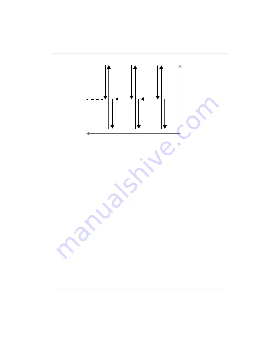
Figure 2-2  Symmetrical scan pattern for a pipe elbow inspection of 360°

In a symmetrical scan pattern, the indexing button is pressed once after completing a 
scan, which stops the acquisition and activates the button’s red LED. Because of its 
“smart indexing” function, the FlexoFORM scanner can then freely move along the 
index axis to the next scan line without overwriting any acquisition data. When the 
scanner is in position at the center of the next scan line (the zero position, or origin), 
the indexing button is pressed once again, and the red LED turns off.

When the indexing button is released at the center of the next scan line, the position of 
encoder 1 is reset to the 

Origin

 parameter value (equivalent to 

Scan > Encoder > 

Origin

). At the same time, the index value will be incremented by a predefined 

distance set in the (encoder 2) 

Resolution

 parameter (see “Setting Up the Scan and 

Index Parameters for an Elbow” on page 31).

To set the parameters for a symmetrical scan

1.

Set the appropriate scan type in the OmniScan MXU software by selecting 

Scan > 

Inspection > Type = Raster Scan

.

2.

In the OmniScan MXU software, set the scanner’s encoder number (1), type 
(Quad), and resolution (12 steps/mm):

a)

Select 

Scan > Encoder > Encoder = 1

.

b)

Select 

Scan > Encoder > Type = Quad

.

c)

Select 

Scan > Encoder > Resolution = 12

.

Scan axis

Index

axis

The initial position of the 
scanner must be at the 
center of each scan line.

Center line

(zero position)

on pipe

Содержание FlexoFORM

Страница 1: ...ual This instruction manual contains essential information on how to use this Olympus product safely and effectively Before using this product thoroughly review this instruction manual Use the product as instructed Keep this instruction manual in a safe accessible location ...

Страница 2: ...he accuracy of the information contained therein and corresponds to the version of the product manufactured prior to the date appearing on the title page There could however be some differences between the manual and the product if the product was modified thereafter The information contained in this document is subject to change without notice Part number 10 003591 01EN Q7780031 Rev 4 January 202...

Страница 3: ...ity 6 Repair and Modification 6 Presence of Visual Interferences 7 Safety Symbols 7 Safety Signal Words 8 Note Signal Words 9 Safety 9 Warnings 9 Equipment Disposal 10 CE European Community 10 WEEE Directive 11 China RoHS 11 Korea Communications Commission KCC 12 KC South Korea Community 12 FCC USA Compliance 13 ICES 001 Canada Compliance 14 Packing and Return Shipping 14 Warranty Information 14 T...

Страница 4: ...ers for an Elbow 31 3 4 Marking the Scan Lines 33 4 Inspection 37 4 1 Wetting the Surface and Purging Air Bubbles 37 4 2 Inspecting a Part 38 4 2 1 Inspecting a Part Using Marked Scan Lines 38 4 2 2 Inspecting a Part without Marked Scan Lines 40 4 3 Correction Factors 41 5 Maintenance and Troubleshooting 45 5 1 Preventive Maintenance 45 5 2 Cleaning the Product 45 5 3 Changing a Magnetic Wheel 46 ...

Страница 5: ...v 4 January 2020 6 5 Dimensions 61 7 Spare Parts and Accessories 65 Appendix A Setting Up to Inspect a Straight Pipe Unidirectional or Bidirectional Scan 75 Appendix B Calculating True Defect Length 77 List of Figures 79 List of Tables 81 Index 83 ...

Страница 6: ...Table of Contents vi 10 003591 01EN Q7780031 Rev 4 January 2020 ...

Страница 7: ... Abbreviations CLK clock EFUP Environment Friendly Use Period ID identification IP International ingress Protection OD outside diameter RH relative humidity RoHS Restriction of Hazardous Substances SDHC secure digital high capacity WEEE Waste Electrical and Electronic Equipment ...

Страница 8: ...10 003591 01EN Q7780031 Rev 4 January 2020 List of Abbreviations viii ...

Страница 9: ... attached to the instrument at the locations shown in Figure i 1 on page 1 If any of the labels or symbols are missing or illegible please contact Olympus Figure i 1 Labels location for scanner Location of scanner rating and address labels see Table 1 on page 2 encoder label not visible between scanner s assembled parts ...

Страница 10: ...s that the product complies with all applicable standards and has been registered with the Australian Communications and Media Authority ACMA for placement on the Australian market Seller and user shall be noticed that this equipment is suitable for electromagnetic equipment for office work class A and it can be used outside the home The MSIP code for the FlexoFORM scanner is the following R R OYN...

Страница 11: ...s for which listed controlled substances will not leak or chemically deteriorate while in the product The EFUP for the FlexoFORM scanner has been determined to be 15 years Note The Environment Friendly Use Period EFUP is not meant to be interpreted as the period assuring functionality and product performance The WEEE symbol indicates that the product must not be disposed of as unsorted municipal w...

Страница 12: ...10 003591 01EN Q7780031 Rev 4 January 2020 Labels and Symbols 4 ...

Страница 13: ...terials Do not use the FlexoFORM scanner for any purpose other than its intended use It must never be used to inspect or examine human or animal body parts Instruction Manual This instruction manual contains essential information on how to use this Olympus product safely and effectively Before using this product thoroughly review this instruction manual Use the product as instructed Keep this inst...

Страница 14: ...accessories that meet Olympus specifications Using incompatible equipment could cause equipment malfunction and or damage or human injury Repair and Modification The FlexoFORM scanner contains user serviceable parts See Maintenance and Troubleshooting on page 45 for information about authorized repairs and maintenance Table 2 Ancillary equipment Part number Description Several available models con...

Страница 15: ...ence depends greatly on the nature strength and proximity of the electromagnetic source and it will only disappear when the source of the noise is no longer emitting signals Safety Symbols The following safety symbols might appear on the instrument and in the instruction manual General warning symbol This symbol is used to alert the user to potential hazards All safety messages that follow this sy...

Страница 16: ...nal word until the indicated conditions are fully understood and met The WARNING signal word indicates a potentially hazardous situation It calls attention to a procedure practice or the like that if not correctly performed or adhered to could result in death or serious personal injury Do not proceed beyond a WARNING signal word until the indicated conditions are fully understood and met The CAUTI...

Страница 17: ... parenthetical information that is useful but not imperative The TIP signal word calls attention to a type of note that helps you apply the techniques and procedures described in the manual to your specific needs or that provides hints on how to effectively use the capabilities of the product Safety Before turning on the instrument verify that the correct safety precautions have been taken see the...

Страница 18: ...ative Do not touch the connectors directly by hand Otherwise a malfunction or electric shock may result Do not allow metallic or foreign objects to enter the device through connectors or any other openings Otherwise a malfunction or electric shock may result Make sure no FlexoFORM scanner components screws straps etc have come loose or are lost in critical equipment being inspected Thoroughly chec...

Страница 19: ...of as unsorted municipal waste but should be collected separately Refer to your local Olympus distributor for return and or collection systems available in your country The China RoHS mark indicates the product s Environment Friendly Use Period EFUP The EFUP is defined as the number of years for which listed controlled substances will not leak or chemically deteriorate while in the product The EFU...

Страница 20: ... Community This device complies with the requirements of KN 61000 6 2 and KN 61000 6 4 concerning electromagnetic compatibility The KC marking indicates compliance with the above standards 产品中有害物质的名称及含量 有害物质 部件名称 铅及其 化合物 汞及其 化合物 镉及其 化合物 六价铬及 其化合物 多溴联苯 多溴 二苯醚 Pb Hg Cd Cr Ⅵ PBB PBDE 机构部件 主体 光学部件 电气部件 附件 本表格依据 SJ T 11364 的规定编制 表示该有害物质在该部件所有均质材料中的含量均在 GB T26572 规定的限量要求以下 表示该有害物质至少在该部件的某一均质材料中的含量超出 GB ...

Страница 21: ...l interference in which case you will be required to correct the interference at your own expense Changes or modifications not expressly approved by the party responsible for compliance could void the user s authority to operate the product FCC Supplier s Declaration of Conformity Hereby declares that the product Product name FlexoFORM Model FlexoFORM X XXX FlexoFORM XXX FlexoFORM XX XXXXX Conform...

Страница 22: ... to returning any units contact Customer Service to obtain the required RMA number s and any important shipping information Follow the steps below to return your FlexoFORM scanner 1 Pack the FlexoFORM scanner back into the transport case that it came in using the original packing materials 2 Include the RMA in the case and reference the RMA number in your shipping documents 3 Close the transport c...

Страница 23: ...in is intended solely as a teaching aid and shall not be used in any particular application without independent testing and or verification by the operator or the supervisor Such independent verification of procedures becomes increasingly important as the criticality of the application increases For this reason Olympus makes no warranty expressed or implied that the techniques examples or procedur...

Страница 24: ...10 003591 01EN Q7780031 Rev 4 January 2020 Important Information Please Read Before Use 16 ...

Страница 25: ... fit the radius of curvature of the surface being inspected The scanner adjusts to hold wedges of various sizes for a range of radius of curvatures Figure i 2 FlexoFORM scanner The FlexoFORM scanner is designed to be used with an OmniScan series instrument For details on instrument and software operation refer to the OmniScan MX and MX2 User s Manual or OmniScan SX User s Manual as well as the Omn...

Страница 26: ...10 003591 01EN Q7780031 Rev 4 January 2020 Introduction 18 ...

Страница 27: ...he FlexoFORM scanner case contents are shown in Figure 1 1 on page 19 Main components are detailed in Figure 1 2 on page 20 Figure 1 1 Case contents Spare parts kit screws o rings etc Allen hexagonal keys user s manual Flexible magnetic straightedge Spare foam gaskets for wedge Line marking template tool Wedge storage compartments 5 FlexoFORM scanner with cable ...

Страница 28: ...gured to hold the following parts for details see Spare Parts and Accessories on page 65 FlexoFORM scanner unit with cable assembly Set of water wedges for a range of inspection surface radii optional Flexible PA probe FA1 Line marking template tool Flexible magnetic straightedge Spare parts kit including screws and o ring seals for probe and water connections Wedge foam gaskets spares Printed cop...

Страница 29: ... outer diameters from 33 mm 1 3 in up to 102 mm 4 in Automated 2D rastering wedge series SFA1 AUTO this wedge series can be used with the SteerROVER or MapROVER motorized scanner to perform automated corrosion inspection of pipes with outer diameters of 218 mm 8 625 in and greater in the longitudinal direction Both SFA1 SMALL and SFA1 AUTO wedges can be fitted with a Mini Wheel encoder from Olympu...

Страница 30: ...10 003591 01EN Q7780031 Rev 4 January 2020 Chapter 1 22 ...

Страница 31: ...le for your requirements you can create a new setup To set up an instrument using a USB key Load the setup from the USB key a Use a computer to transfer the setup from the supplied USB key to the OmniScan instrument s SDHC memory card b Insert the SDHC card into the OmniScan and then turn it on c Select the setup 2 2 Setting Up an Instrument Using the Interface Most common setups can be easily cre...

Страница 32: ... 2 1 on page 24 Although the probe has a concave shape it is important to select Plate even if you are inspecting a curved surface Figure 2 1 Selecting Plate in the Specimen Type field 2 2 2 Setting the Parameters for a Symmetrical Scan For pipe elbow inspections Olympus recommends the symmetrical scan pattern for a full 360 inspection around the circumference see Figure 2 2 on page 25 The OmniSca...

Страница 33: ...xing button is released at the center of the next scan line the position of encoder 1 is reset to the Origin parameter value equivalent to Scan Encoder Origin At the same time the index value will be incremented by a predefined distance set in the encoder 2 Resolution parameter see Setting Up the Scan and Index Parameters for an Elbow on page 31 To set the parameters for a symmetrical scan 1 Set t...

Страница 34: ... Select Preferences Category DIN b Select Preferences Select DIN DIN 3 and set the state Select DIN3 Assign DIN Acquisition State Select DIN3 State On 2 3 Installing the Probe and Wedge Because of its design the flexible phased array probe can be easily damaged if handled incorrectly It is not recommended to bring the probe into direct contact with a part The probe should only be shaped using an O...

Страница 35: ...wheel safety The magnetic fields around the wheels may affect pacemakers watches and other sensitive electronic devices and anyone relying on such devices must keep a safe distance away from the wheels to avoid the risk of serious injury or death Magnetic wheels present a risk of finger crushing if fingers are placed between the wheels and a ferromagnetic surface The wheels may suddenly attract fe...

Страница 36: ...ner To connect the scanner 1 Connect the LEMO encoder cable to the OmniScan instrument see Figure 2 4 on page 28 2 Connect the probe cable to the OmniScan instrument 3 Connect the water supply to an Olympus couplant feed unit For more details on the recommended CFU03 pump connection refer to the CFU03 CFU05 CFU PWZ Couplant Feed Unit User s Manual Figure 2 4 Scanner connections example Note Water ...

Страница 37: ...rve the following precautions when handling the FlexoFORM scanner To prevent injury and equipment damage when operating the FlexoFORM scanner at heights 2 meters or higher above ground or floor level secure it with a lanyard that is held taut see attachment point in Figure 3 1 on page 30 Wear appropriate safety shoes that protect your feet in case you accidentally drop the unit during handling Als...

Страница 38: ...al impact 3 2 Cleaning the Inspection Surface The inspection surface must be free of scaling and other obstructions A smooth surface helps maintain the water column and extends the life of the wedge s foam gasket that rubs against the surface during inspection To avoid the risk of injury wear appropriate work gloves and safety glasses when cleaning the inspection surface using scrapers metal brush...

Страница 39: ...your elbow size These are determined by your probe s effective beam width elbow dimensions and desired scan overlap To set up the scan and index parameters for an elbow 1 Measure and record your elbow s extrados maximum outer elbow curve length on surface see Figure 3 2 on page 31 Figure 3 2 Extrados maximum outer elbow curve length 2 Set the scan parameters a Divide the extrados value by two and ...

Страница 40: ...s value at right in Figure 3 3 on page 32 should therefore not be used but instead you must obtain a value using Table 3 on page 42 For more details and alternative calculation see Correction Factors on page 41 For example for a 559 mm 22 in OD pipe and a focal law of 4 elements Table 3 on page 42 provides an effective beam width value of 58 1 mm on the surface If the desired overlap is 2 mm then ...

Страница 41: ...ave been covered by the scan Therefore Linear at 0 mode is recommended 3 4 Marking the Scan Lines Before an inspection it is recommended that you lay out and mark scan lines to follow when moving the FlexoFORM scanner over a surface The steps for determining the line length and spacing for an elbow are detailed in Setting Up the Scan and Index Parameters for an Elbow on page 31 However it is also ...

Страница 42: ... package to help you draw scan lines The supplied tool has markings that help you draw a line a distance of 48 mm to 58 mm from the previous line 4 Insert a paint marker pen into the hole in the template marking tool then use the tool s markings as a guide to follow the first scan line and draw your next scan line at the required index distance see Figure 3 6 on page 35 Draw the remainder of the s...

Страница 43: ... 2020 Preparation for Inspection 35 Figure 3 6 Drawing the scan lines on an elbow Hole for paint marker Scan line drawn by the paint marker Required indexing distance Template marking tool and paint marker Distance markings in millimeters ...

Страница 44: ...10 003591 01EN Q7780031 Rev 4 January 2020 Chapter 3 36 ...

Страница 45: ...urface and clear air from the water column between the inspection surface and the probe To wet the surface and purge air bubbles 1 Wet the surface for example by using a cloth soaked with water 2 Open the water supply and then position the FlexoFORM scanner on the inspection surface 3 Move the scanner back and forth and sideways if necessary over the inspection surface to help clear air bubbles 4 ...

Страница 46: ...s 4 2 1 Inspecting a Part Using Marked Scan Lines Use the following procedure if you have marked scan lines on your part surface To inspect a part using marked scan lines 1 Position the FlexoFORM scanner so that it is aligned with the first marked scan line and the start zero position see Figure 4 2 on page 39 Use the wedge s alignment mark and the encoder wheel to align on the scan line Use the a...

Страница 47: ...nner over and align it on the next scan line and on the zero position line as detailed in step 1 6 Press the indexing button again releasing it from indexing to restart the acquisition increment increase the index position and reset the scan position To avoid the risk of overwriting a small portion of your acquisition data wait at least one second after having pressed and released the button befor...

Страница 48: ...similar except for the starting marks To inspect a part without marked scan lines 1 Align the FlexoFORM scanner on the zero position line around the pipe circumference using the alignment marks on the sides between the wheels 2 Use a pen to make a mark on the pipe at probe element 1 see Figure 4 4 on page 41 and another mark at element 64 Offset the marks towards the center of the scanner by an am...

Страница 49: ... second after having pressed the button before moving to avoid the risk of overwriting your data 8 Repeat the above steps 4 7 until you complete all necessary inspection scans 4 3 Correction Factors The probe s concave shape its distance away from the inspection surface and the number of elements in its beam affect the effective probe beam width and observed defect size in the following ways The e...

Страница 50: ... 39 5 38 8 38 2 37 5 36 9 36 2 1 66 42 6 41 9 41 2 40 5 39 8 39 1 1 9 44 3 43 6 42 8 42 1 41 4 40 7 2 375 46 9 46 1 45 3 44 6 43 8 43 2 875 48 8 48 47 2 46 4 45 6 44 8 3 5 50 6 49 8 49 48 1 47 3 46 5 4 51 7 50 9 50 49 2 48 3 47 5 4 5 52 6 51 8 50 9 50 49 2 48 3 6 625 55 54 1 53 2 52 3 51 4 50 5 8 625 56 3 55 4 54 5 53 6 52 6 51 7 10 75 57 2 56 3 55 3 54 4 53 4 52 5 12 75 57 8 56 8 55 9 54 9 54 53 ...

Страница 51: ...pths in typical inspection applications For example if a defect is measured to be 10 mm long along the index axis 6 mm below the surface on a 114 mm 4 5 in pipe the multiplication factor is 0 77 and the true defect length 10 mm 0 77 7 7 mm For inspection applications that fall outside the range of the table the true defect length can be calculated as shown in Calculating True Defect Length on page...

Страница 52: ... 0 81 0 80 0 78 0 76 0 75 0 73 0 71 0 70 0 68 4 5 0 83 0 82 0 80 0 79 0 77 0 76 0 74 0 73 0 71 6 625 0 88 0 87 0 86 0 85 0 84 0 83 0 82 0 81 0 80 8 625 0 91 0 90 0 89 0 88 0 87 0 86 0 86 0 85 0 84 10 75 0 92 0 92 0 91 0 90 0 90 0 89 0 88 0 88 0 87 12 75 0 94 0 93 0 92 0 92 0 91 0 91 0 90 0 89 0 89 16 0 95 0 94 0 94 0 93 0 93 0 92 0 92 0 91 0 91 22 0 96 0 96 0 95 0 95 0 95 0 94 0 94 0 94 0 93 26 0 ...

Страница 53: ...egular inspection of the scanner is recommended to ensure that it is functioning correctly If necessary clean the scanner or clean and or change the wheels as outlined below Monitor the condition of the foam gasket and the water seals and replace as needed as outlined below 5 2 Cleaning the Product The FlexoFORM scanner s external surfaces may be cleaned when needed To clean the product 1 Turn off...

Страница 54: ...sure that the connectors are dry before reconnecting them If they are not dry either dry them off using compressed air or wait until they dry on their own 5 3 Changing a Magnetic Wheel Depending on use it may be necessary to periodically change the magnetic wheels The magnetic attraction forces around the magnetic wheels may pose certain safety risks depending on use and operating conditions The m...

Страница 55: ... on page 49 Be careful while using tools around magnetic wheels and while holding or moving the wheels Tools wheels or other ferromagnetic objects in the vicinity may suddenly move and forcefully be attracted to each other which could potentially cause injury or equipment damage Be sure to allow sufficient free space around equipment and tools to prevent sudden attractive forces between them The F...

Страница 56: ...side then carefully pull out the shaft while holding the wheel to counteract the magnetic repulsive force and then pull out the wheel with its bearings 3 Similarly see steps 1 and 2 remove the wheel next to it on the same side of the scanner 4 Install the first new wheel with its bearings and tighten the screw 5 Install the second new wheel by carefully pushing against it to counteract the magneti...

Страница 57: ...hen handling magnetic wheels take note of the magnetic attraction forces around the wheels and observe the safety notes outlined in Changing a Magnetic Wheel on page 46 To clean the magnetic wheels 1 Put on your work gloves 2 Apply clean adhesive tape to the wheel then pull the tape off to remove particles and if necessary repeat until all particles have been removed This is the recommended wheel ...

Страница 58: ...der and insert and tighten the screws Olympus recommends Loctite 425 thread locker because it will not damage plastic parts in the vicinity if inadvertently spilled Figure 5 2 Changing the encoder 5 6 Changing the Foam Gasket and the O ring Seals The foam gasket on the wedge which maintains the water column must be changed periodically depending on inspection conditions and surface roughness The o...

Страница 59: ...dhesive side of the gasket with the mounting surface and then press it against the surface to install it Figure 5 3 Changing the foam gasket To change the o ring seal between the probe and wedge 1 Use an appropriate tool such as a small flathead screwdriver to carefully lift and pull off the old o ring seal without damaging the mounting surface on the wedge see Figure 5 4 on page 52 2 Install the ...

Страница 60: ... mounting surface see Figure 5 5 on page 52 2 Install the new o ring seal Figure 5 5 Changing the o ring seal for the water connection 5 7 Changing the Water Tube The water tube on the scanner can be changed if it is damaged To change the water tube 1 Remove the screw that fixes the water connector to the scanner see Figure 5 6 on page 53 2 Pull the connector off the water tube 3 Pull back the cab...

Страница 61: ...onnector and then close the cable sleeve Figure 5 6 Changing the tube shown disassembled 5 8 Changing the Cable Sleeve To change the cable sleeve you must partially disassemble the scanner on one side including two magnetic wheels see Figure 5 7 on page 55 To avoid injury or equipment damage when handling the magnetic wheels take note of the magnetic attraction forces around the wheels and observe...

Страница 62: ...e detailed in Changing a Magnetic Wheel on page 46 Be aware of magnetic forces that can suddenly attract or repulse parts 2 Remove the screws that hold the scanner end piece and pull it away 3 Remove the screws on the bracket and pull the sleeve out of the end piece 4 Follow the steps in reverse order to reinstall the new sleeve and securely tighten all screws ...

Страница 63: ... 4 January 2020 Maintenance and Troubleshooting 55 Figure 5 7 Disassembly steps for changing the cable sleeve 5 9 Troubleshooting Table 5 on page 56 lists some problems that may arise possible causes and suggested solutions 1 2 3 ...

Страница 64: ...are crashes Wrong software was loaded Shut down the instrument and restart with correct software No C scan displayed There is no encoder connection Check encoder connections between FlexoFORM scanner and instrument Black lines on C scan Scanning is too fast Reduce scanning speed Scanner does not open and close easily during wedge change Mechanism contains dirt or foreign particles Gently rinse the...

Страница 65: ...a flat surface Probe Type FA1 64 elements flexible Cable length 5 m Center frequency 7 5 MHz Part number Q3301201 Wedges Type SFA1 Flexo multiple models for a range of inspection surface radii see Table 7 on page 59 and Table 12 on page 71 Alternative wedges for inspections without a FlexoFORM scanner are described in Alternative Components on page 21 and listed in Table 13 on page 72 and Table 14...

Страница 66: ...t from the wheels below the 2 milligauss limit at which restrictions would be imposed on air shipment Encoder Recommended scanning speed variable dependent on OmniScan instrument and application setup used Type Quadrature Resolution 12 steps mm 0 15 steps mm Wet locations Water resistant IP55 Pinout See Figure 6 1 on page 61 Voltage 5 VDC Maximum current 100 mA CLK frequency 1 MHz Environment Outd...

Страница 67: ...n OD in Max OD in 4 5 4 4 4 5 5 563 5 4 5 6 6 625 6 4 6 8 8 625 8 3 8 8 10 75 10 3 11 1 11 75 11 1 12 1 12 75 12 1 13 3 14 13 1 14 6 16 14 9 16 8 18 16 6 18 9 20 18 4 21 1 22 20 1 23 4 24 21 7 25 7 26 23 3 28 28 24 9 30 3 30 26 4 32 7 32 28 35 1 34 29 5 37 4 36 31 3 39 6 38 32 5 42 4 42 35 4 47 4 48 39 6 55 1 Flat 200 Flat ...

Страница 68: ...t plates Circumferential inspection of pipes With 48 in and up outside diameters With 20 in and up inside diameters Longitudinal inspection of pipes With 200 in and up outside diameters The FlexoFORM scanner cannot be used to perform longitudinal inspection of pipes on the inside surface 6 4 Cable Connector Pinout The connector pinout for the scanner interface cable is shown in Figure 6 1 on page ...

Страница 69: ...pin to 16 pin 6 5 Dimensions The FlexoFORM scanner dimensions are shown in Figure 6 2 on page 62 DIN3 PHA 1 PHB 1 GND 5 V IN Shield drain Housing Housing PHA 2 Brown Green Orange Black Red Yellow Solder side view FGG 1K 316 CLAC50Z Solder side view FGG 0T 305 CLAC50Z OmniScan instrument FlexoFORM scanner ...

Страница 70: ...s The SFA1 SMALL wedge series dimensions and clearances are shown in Figure 6 3 on page 63 Figure 6 4 on page 64 and in Table 8 on page 64 100 98 2 mm 3 87 in 260 6 mm 10 26 in 193 mm 7 6 in 100 mm 3 94 in 93 1 mm 3 66 in 101 6 mm 4 00 in 52 5 mm 2 07 in 28 7 mm 1 13 in 38 9 mm 1 53 in ...

Страница 71: ... 003591 01EN Q7780031 Rev 4 January 2020 Specifications 63 Figure 6 3 SFA1 SMALL wedge clearances Circumferential clearance Probe side clearance Height clearance Length Pipe diameter Water side clearance ...

Страница 72: ... 108 421 117 594 122 098 128 089 131 261 133 042 133 592 111 737 Circumfer ential clear ance mm 160 537 170 563 176 208 185 836 195 147 206 707 216 223 226 052 Height clearance mm 38 5 38 5 38 5 38 5 38 5 38 5 38 5 38 5 Water side clearance mm 28 995 30 964 31 383 30 502 27 312 21 645 16 374 10 726 Probe side clearance mm 46 025 44 47 42 455 37 261 30 919 22 498 15 618 8 711 Width mm 95 95 95 95 9...

Страница 73: ...ORM scanner is shown in Figure 7 1 on page 65 A list of standard spare parts is provided in Table 9 on page 66 Accessories and spare part kits are listed in Table 11 on page 70 to Table 14 on page 73 Figure 7 1 Scanner exploded view 8 10 11 17 12 22 36 27 28 6 33 29 32 9 30 7 5 4 2 3 1 34 35 5 21 5 18 5 5 31 14 19 16 23 26 25 24 20 15 ...

Страница 74: ...ead stainless N A 11 Q8301429 1 Name plate N A 12 Q8301430 1 Shaft threaded N A 13 Q8301432 1 Wiper ring N A 14 Q8301433 1 Encoder FlexoFORM N A 15 Q8301481 1 Encoder base front N A 16 Q8301482 1 Encoder base back N A 17 Q8301426 4 Lock washer internal tooth M2 N A 18 N Aa 4 Screw M2 6 mm hex head stainless N A 19 Q8301431 1 Encoder wheel N A 20 U8909086 2 Bearing flanged 8 mm ID 12 mm OD 3 5 mm W...

Страница 75: ...lexoFORM scanner without probe wedges carrying case spare part and accessories for corrosion inspection of pipe elbows Package includes irrigation tubes as well as encoder cable with LEMO connector compatible with current generation of OmniScan and FOCUS PX instruments Cable and tube are 5 m long Requires FA1 probe and SFA1 water wedges which are ordered separately FlexoFORM SCN N A Q8000207 N A F...

Страница 76: ...exploded view of the SFA1 AUTO and SFA1 SMALL wedges A list of spare parts for these wedges is provided in Table 10 on page 69 N A Q8301466 N A Allen key 2 mm N A N A Q8301467 N A Allen key 1 5 mm N A a Item included in spare parts kit P N Q7500064 Table 9 Spare parts continued Item Part order number Qty Description Marketing number ...

Страница 77: ...it of 10 o ring seals for probe on wedge N A 2 Q7500066 Kit of 12 foams for SFA1 AUTO water wedges Compatible with pipe diameters of 8 625 in OD and up FLEXOFORM SP LFOAM Q7201701 Kit of ten 10 foams for SFA1 SMALL OD1 3 water wedge SFA1 SMALL SP Foam OD1 3 Q7201702 Kit of ten 10 foams for SFA1 SMALL OD1 66 water wedge SFA1 SMALL SP Foam OD1 66 Q7201703 Kit of ten 10 foams for SFA1 SMALL OD1 9 wat...

Страница 78: ...e includes encoder cable with LEMO connector compatible with current generation of OmniScan and FOCUS PX instruments irrigation tube basic spare parts and accessories packaged in a carrying case Cable and tube are 5 m long Requires FA1 probe and SFA1 water wedges which are ordered separately FlexoFORM K SCN Q7500062 FlexoFORM scanner kit for corrosion inspection of pipe elbows Package includes Fle...

Страница 79: ... Marketing number Q7500067 Standard wedge for flexible array probe FA1 and compatible with FlexoFORM scanner The wedge is used to generate 0 longitudinal waves and features a curvature matching 114 mm 4 5 in OD for inspection of extrados and intrados of pipe elbows The wedge also features a 9 mm high water column allowing inspection of up to 30 mm thick carbon steel materials SFA1 Flexo OD4 5 Q750...

Страница 80: ...R scanners The wedge is used to generate 0 Longitudinal waves and features a curvature matching 219 mm 8 625 in OD for inspection of extrados and intrados of pipe elbows The wedge also features a 9 mm high water column allowing inspection of up to 30 mm thick carbon steel materials Not compatible with FlexoFORM scanner SFA1 Auto OD8 625 Q7500089 As above but for 273 mm 10 75 in pipe OD SFA1 Auto O...

Страница 81: ...Not suitable for inspection of elbow intrados The wedge is used to generate 0 Longitudinal waves and features a curvature matching 33 4 mm 1 315 in outside diameter OD for inspection of elbow extrados The wedge also features an 11 mm high water column allowing inspection of up to 35 mm thick carbon steel materials Compatible with the Mini Wheel encoder Not compatible with FlexoFORM scanner SFA1 Sm...

Страница 82: ...10 003591 01EN Q7780031 Rev 4 January 2020 Chapter 7 74 ...

Страница 83: ...ces Olympus recommends the unidirectional or bidirectional scanning methods for straight pipe or cylinder surfaces Unidirectional scan The principal advantage of performing a unidirectional scan is that the same starting reference is retained for each scan because the encoder in the scan direction is always reset to the origin value every time the indexing button is pressed see Figure A 1 on page ...

Страница 84: ...irectional scan pattern To set up for a bidirectional scan 1 Set the scan encoder and input parameters according to steps 1 2 and 4 in To set the parameters for a symmetrical scan on page 25 2 Set the indexing button s encoder number 2 and type Clicker a Select Scan Encoder Encoder 2 b Select Scan Encoder Type Clicker A bidirectional scan differs from a symmetrical scan as follows The scan start v...

Страница 85: ...n page 77 The variables are illustrated in Figure B 1 on page 77 Figure B 1 Variables for calculating true defect length along the index axis 2 Lo True defect length l Measured defect length Ro Outside radius h Water column height 9 mm for SFA1 FLEXO and SFA1 AUTO wedge series and 11 mm for SFA1 SMALL wedge series d Measured depth of defect t Thickness of material reference only L0 Ro d l Ro h ...

Страница 86: ...10 003591 01EN Q7780031 Rev 4 January 2020 Appendix B 78 ...

Страница 87: ...ution setting in the OmniScan 32 Figure 3 5 Marking the zero position left and scan right lines on an elbow 34 Figure 3 6 Drawing the scan lines on an elbow 35 Figure 4 1 An example S scan display free of bubbles 38 Figure 4 2 Alignment marks 39 Figure 4 3 Scan pattern for a pipe elbow 40 Figure 4 4 Probe element marks on the wedge 41 Figure 4 5 Variables for calculating probe beam width on the su...

Страница 88: ...ure 7 1 Scanner exploded view 65 Figure 7 2 Basic spare parts kit P N Q7500064 68 Figure 7 3 SFA1 AUTO and SFA1 SMALL wedges exploded view 69 Figure A 1 Unidirectional scan pattern 75 Figure A 2 Bidirectional scan pattern 76 Figure B 1 Variables for calculating true defect length along the index axis 77 ...

Страница 89: ...h correction along index axis 44 Table 5 Troubleshooting guide 56 Table 6 General specifications 57 Table 7 Range of pipe diameters covered by each wedge 59 Table 8 SFA1 SMALL wedge series dimensions and clearances 64 Table 9 Spare parts 66 Table 10 SFA1 wedge spare part list 69 Table 11 FlexoFORM scanner and probe kits 70 Table 12 FlexoFORM standard wedges 71 Table 13 Wedges for automated inspect...

Страница 90: ...10 003591 01EN Q7780031 Rev 4 January 2020 List of Tables 82 ...

Страница 91: ...dge in scanner 30 CE European Community 10 CE marking 2 China RoHS 3 11 cleaning general 45 inspection surface 30 magnetic wheels 49 compatibility instrument 6 compliance CE 2 FCC USA 13 ICES 001 Canada 14 RCM Australia 2 connection scanner 28 connector pinout 60 correction factors 41 D DANGER signal word 8 defect length calculation 77 dimensions scanner 61 direct current symbol 3 disposal equipme...

Страница 92: ...and software 17 modification industrial inspection system 6 N NOTE signal word 9 notes information signal words 9 O Olympus technical support 15 overlap of scan 33 overview scanner 19 P pacemaker warning 47 packing and return shipping 14 parts spare 65 pinout connector 60 precautions drop 29 general safety 9 preparation cleaning inspection surface 30 scan lines 33 probe caution handling 26 install...

Страница 93: ...s 1 CE 2 direct current 3 Korean standard 2 RCM Australia 2 RoHS 3 11 safety 7 warning 3 WEEE 3 T technical support 15 TIP signal word 9 troubleshooting 55 U unidirectional scan 75 use intended 5 V visual interference 7 W WARNING signal word 8 warning symbols finger crushing 7 general 7 magnetic field 8 marking 3 warnings accidental drop 29 general 9 magnetic field 47 misuse of instrument 5 pacema...

Страница 94: ...10 003591 01EN Q7780031 Rev 4 January 2020 Index 86 ...

Отзывы: