


Installation
In order to meet EMC requirements , connections of peripherals to the panel must be done using
shielded cables.
(220-240V AC)
The panel has holes on the back side for all the wiring to pass through. You can connect cables with
max.
c
onductor diametre of 2.5mm to the panels terminal blocks.
The mains power supply wiring must use a double insulation cable.
The connection with the mains power supply must be done to the terminal
blocks located on the panels up left area Figure 8 .
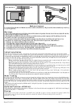
Battery connection
The battery compartment has the appropriate dimensions
for
Α-9
20
batter
ies
of
Ol
ympia
E
lectronics
.
The charging unit on PCB is also calculated for the specific batter
ies
.
Replace the
m
only with batter
ies
of the same type.
From the PCB, are connected two battery wires with a special terminal on the
edge. They must be connected to the two battery poles. Connect
t
he black wire
to the negative pole (marked (-)
or a black mark)
,
the red wire to positive pole
(marked
(+) or a red mark)
and connect the included wire for the link as showed
in the side figure
.
The installation of the panel must be carried out by qualified personnel only.
Disconnect power before servicing.
Never insert or remove boards or componets with the power on.
During installation use grounded antistatic wrist band to protect this equi
p
ment form ESD.
The panel must be installed permanetly. It is not allowed to connect the device directly to any socket-
outlet.
Mounting the panel to the wall
The site chosen for the location of the panel should be clean and dry and not subject to shock or
vibration.
In page 1 shows the mounting holes of the panel.
The panel must be placed above 1m from the floor and and 1m below the ceiling and must have
distance 30cm from any other devices. No other power lines must pass behind the panel, only the
supply cables of the panel.
Cabling
Each screen or shield braid must properly be connected to the earth terminal block provided, thus
ensuring the shortest posible path.
The maximum conductor diameter size, which can be
us
ed, is 2,5mm²
Connecting the mains power supply
The main supply must include an earth conductor connected to the fixed installation
earthing system of the building.
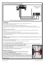
Figure 7.
Connection diagram of BS-489 telephone operator.
-
+
24_P
Fire Detection
Panel
Connecting the BS-489 telephone operator
Page 7 from
10
NO
ALARM
C NC NO
FAULT
C NC
Panel connection
Link
921163600_09_020