background image

2H0/2HZ

1-3-23

U051

Adjusting the deflection in the paper
Description

Adjusts the deflection in the paper.

Purpose

Make the adjustment if the leading edge of the copy image is missing or varies randomly, or if the copy paper 
is Z-folded.

Adjustment

1. Press the start key.
2. Select the item to be adjusted.

3. Press the system menu key.
4. Place an original and press the start key to make a test copy.
5. Press the system menu key.
6. Change the setting value using the +/- or numeric keys.

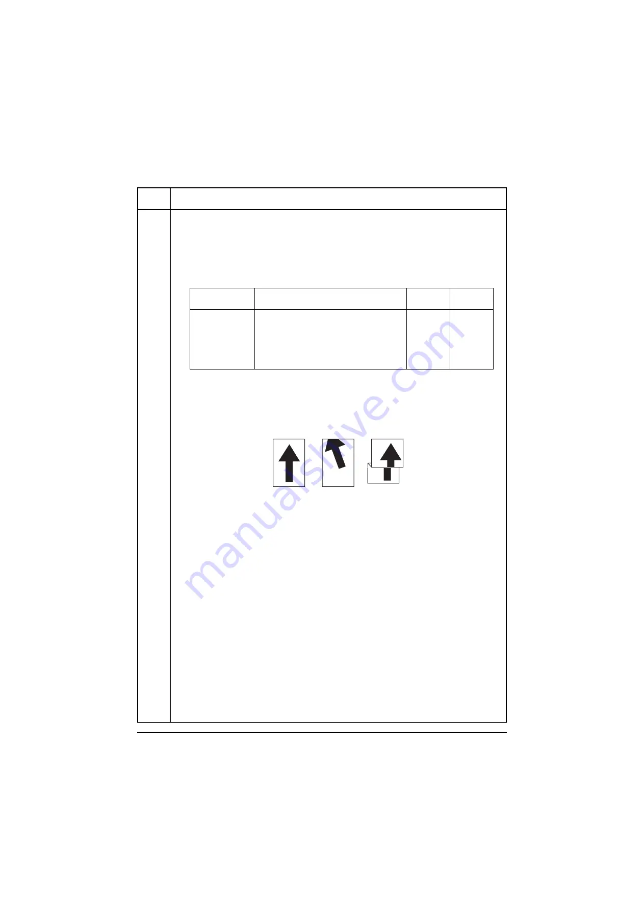
For output example 1, increase the value. For output example 2, decrease the value.
The greater the value, the larger the deflection; the smaller the value, the smaller the deflection.

Figure 1-3-7

7. Press the start key. The value is set.

Completion

Press the stop key. The indication for selecting a maintenance item No. appears.

Maintenance

item No.

Description

Display

Description

Setting
range

Initial
setting

MP TRAY

Paper feed from MP tray

-50 to 127

0

CASSETTE

Paper feed from cassette 1

-50 to 127

50

CASSETTE2

Paper feed from cassette 2

-50 to 127

50

DUPLEX

Duplex mode (second side)

-50 to 127

40

MP TRAY (THICK)

Paper feed from MP tray (thick paper)

-50 to 127

10

Original

Copy

example 1

Copy

example 2

Y108620-5                                                                  Service Manual

Содержание d-Copia 2500MF

Страница 1: ...d Copia 2500MF d Copia 3000MF Digital Copier SERVICE MANUAL Code Y108620 5...

Страница 2: ...PUBLICATION ISSUED BY Olivetti S p A 77 Via Jervis 10015 Ivrea TO Italy Copyright 2007 Olivetti All rights reserved...

Страница 3: ...icials for details in your area for proper disposal ATTENTION IL Y A UN RISQUE D EXPLOSION SI LA BATTERIE EST REMPLACEE PAR UN MODELE DE TYPE INCORRECT METTRE AU REBUT LES BATTERIES UTILISEES SELON LE...

Страница 4: ...This page is intentionally left blank...

Страница 5: ...sonnel to ensure the safety of their customers their machines as well as themselves during maintenance activities Service personnel are advised to read this booklet carefully to familiarize themselves...

Страница 6: ...this symbol CAUTION Bodily injury or damage to property may result from insufficient attention to or incorrect compliance with warning messages using this symbol Symbols The triangle symbol indicates...

Страница 7: ...or dusty place This may cause fire or electric shock Do not install the copier near a radiator heater other heat source or near flammable material This may cause fire Allow sufficient space around the...

Страница 8: ...carefully Always check that the copier is correctly connected to an outlet with a ground connection Check that the power cable covering is free of damage Check that the power plug is dust free If it i...

Страница 9: ...trapped wire and missing screws Check that all the caution labels that should be present on the machine according to the instruction handbook are clean and not peeling Replace with new ones if necess...

Страница 10: ...This page is intentionally left blank...

Страница 11: ...ddress Book Adding One Touch Keys 1 3 93 12 User login administration 1 3 94 13 Job accounting 1 3 95 1 4 Troubleshooting 1 4 1 Paper misfeed detection 1 4 1 1 Paper misfeed indication 1 4 1 2 Paper m...

Страница 12: ...tting the main charger unit 1 5 36 3 Detaching and refitting the drum separation claws 1 5 37 1 5 5 Developing section 1 5 38 1 Detaching and refitting the developing unit 1 5 38 1 5 6 Transfer sectio...

Страница 13: ...1 17 1 Paper conveying operation in duplex copying 2 1 19 2 2 Electrical Parts Layout 2 2 1 Electrical parts layout 2 2 1 1 PWBs 2 2 1 2 Switches and sensors 2 2 3 3 Motors 2 2 5 4 Clutches and soleno...

Страница 14: ...2H0 2HZ This page is intentionally left blank...

Страница 15: ...el A3 Ledger 12 5 sheets min B4 Legal 12 5 sheets min A4 Letter 25 sheets min A4R LetterR 17 5 sheets min B5 25 sheets min B5R 20 sheets min A5R 14 sheets min 30 ppm model A3 Ledger 15 sheets min B4 L...

Страница 16: ...600 dpi Fast 1200 mode Applicable OS Microsoft Windows 95 98 Me 2000 XP Microsoft Windows NT4 0 Microsoft Windows Server 2003 Microsoft Windows Vista Apple Macintosh OS 8 x 9 x X Interface Hi speed US...

Страница 17: ...ette 1 12 Cassette 2 13 Toner container 14 Toner container stopper 15 Cleaner rod 16 Waste toner box 17 Cleaning brush 18 Knob A1 19 Paper feed unit A2 20 Paper feed unit cover A3 21 USB memory slot 2...

Страница 18: ...7 Error indicator 8 Help key indicator 9 Logout key indicator 10 Energy saver key indicator 11 Power key indicator 12 Main power indicator 13 Status Job cancel key indicator 14 Program key indicator 1...

Страница 19: ...ath Light path 3 8 9 7 6 2 5 4 1 1 1 3 1 Paper feed section 2 Main charging section 3 Optical section 4 Developing section 5 Transfer and separation section 6 Cleaning and charge erasing section 7 Fus...

Страница 20: ...2H0 2HZ 1 1 6 This page is intentionally left blank Service Manual Y108620 5...

Страница 21: ...machine Avoid dust and vibration Choose a surface capable of supporting the weight of the machine Place the machine on a level surface maximum allowance inclination 1 Avoid air borne substances that m...

Страница 22: ...r cord Installing toner Install other optional devices Install the optional original cover or the DP Print out the user setting list Make test copies Output an own status report maintenance item U000...

Страница 23: ...ng the machine When moving the machine pull out the four carrying handles on the right and left sides and hold them Figure 1 2 2 Carrying handle Carrying handle Carrying handle Carrying handle Y108620...

Страница 24: ...frame 4 Skid 5 Bottom front left pad 6 Bottom front right pad 7 Bottom rear left pad 8 Bottom rear right pad 9 Bottom pad 10 Top pad 11 Machine cover 12 Document tray 13 Power cord 14 Plastic bag 15...

Страница 25: ...2H0 2HZ 1 2 5 1 Remove the eject spacer 2 Remove four tapes Figure 1 2 4 Remove the eject spacer and tapes Tape Tape Eject spacer Tape Tape Y108620 5 Service Manual...

Страница 26: ...apes 2 Remove two scanner pins Figure 1 2 5 1 Pull cassette 1 and 2 out Remove the lift plate stopper from each cas sette and attach it to the storage location When moving the machine attach the lift...

Страница 27: ...igure 1 2 7 2 Adjust the paper length guide to fit the paper size Figure 1 2 8 3 Align the paper flush against the left side of the cassette Figure 1 2 9 4 Gently push cassette 1 and 2 back in Load pa...

Страница 28: ...times or more Figure 1 2 10 3 Shake the toner container up and down five times or more Turn the toner container upside down and shake it five times or more Figure 1 2 11 4 Shake the toner container a...

Страница 29: ...te toner box in the machine 2 Close the front cover Figure 1 2 14 1 Install the optional original cover or DP 1 Install the optional devices job separator built in finisher document finisher and or fa...

Страница 30: ...the start key 4 Select MAINTENANCE and press the start key to output a list of the current settings of the maintenance items 5 Press the stop key 1 Enter 001 using the numeric keys and press the start...

Страница 31: ...Double count A3 LGR U260 Selecting the timing for copy counting After ejection U285 Setting service status page ON U324 Setting the main charger cleaning indication ON U326 Setting the black line cle...

Страница 32: ...screws Procedure 1 Press the power key on the operation panel to off Make sure that the power indicator and the memory indicator are off before turning off the main power switch And then unplug the po...

Страница 33: ...8 Seat the fook of the key counter cover retainer in the aperture in the right upper cover 9 Fit the key counter cover retainer using two screws Figure 1 2 17 Screw Screw Scanner right cover Right up...

Страница 34: ...between the scanner right cover and the upper right cover Figure 1 2 19 16 Insert the key counter into the key counter socket assembly 17 Turn the main power switch on and enter the maintenance mode...

Страница 35: ...sing the cursor up down keys or numeric keys and press the start key Enter the maintenance item number using the cursor up down keys or numeric keys The selected maintenance item is run Press the stop...

Страница 36: ...0 1 U053 Setting the adjustment of the motor speed 0 1 2 0 2 8 0 1 U055 Setting the motor periodic drive ON 1 U059 Setting fan mode 45 1 Optical U061 Turning the exposure lamp on U063 Adjusting the sh...

Страница 37: ...ng the fuser temperature Operation panel and support equipment U200 Turning all LEDs on U201 Initializing the touch panel U202 Setting the KMAS host monitoring system U203 Checking DP operation U204 S...

Страница 38: ...2 Metric specifications OFF 1 2 Others U901 Checking clearing copy counts by paper feed locations U903 Checking clearing the paper jam counts U904 Checking clearing the service call counts U905 Check...

Страница 39: ...ware version 2H0_2L00 P01 006 Paper Jam Log Counter Log 2007 05 22 J04 000 J05 000 J09 000 J10 000 J11 002 J12 000 J13 000 J14 000 J15 000 J20 000 J21 000 J22 000 J23 000 J30 002 J40 002 J41 000 J42 0...

Страница 40: ...tration transfer section 40 Misfeed in fuser section MP tray 41 Misfeed in fuser section cassette 1 42 Misfeed in fuser section cassette 2 43 Misfeed in fuser section optional cassette 3 44 Misfeed in...

Страница 41: ...12 8 27 8K 28 16K R A8 16K E 32 Statement R B2 Statement E 33 Folio 34 Western type 2 35 Western type 4 d Detail of paper type Hexadecimal 00 Not specified 01 Plain 02 Transparency 03 Preprint 04 Labe...

Страница 42: ...nknown Toner Log Count Item Remembers 1 to 5 of occurrence of unknown toner detection If the occurrence of the previ ous unknown toner detection is less than 5 all of the unknown toner detection are l...

Страница 43: ...Time Server 01 00_Amsterdam 05 22 2007 09 06 10 183 53 13 FRPO Status User Top Margin User Left Margin User Page Length A1 A2 100 A3 A4 100 A5 A6 100 0 00 0 00 17 30 Auto Continue Mode Auto Continue...

Страница 44: ...OFF TX 4db 0db 43dBm 9dBm Installed Options Document Processor Paper Feeder Finisher Mail Box Job Separator Memory Card PDF Expansion Kit Fax Backup Kit Security Kit Data Security Kit C Software Secu...

Страница 45: ...ate and output date 18 Page of relation to the A4 Letter 19 Average coverage Total Copy Printer Fax 20 Coverage on the final output page 21 Presence or absence of the optional DP Installed Not Install...

Страница 46: ...ance item U024 and execute initialization using maintenance item U002 For other errors occurred turn main power switch off then on and execute initialization using maintenance item U002 Maintenance it...

Страница 47: ...e machine Method 1 Press the start key 2 Select the item to be operated 3 Press the start key 4 Press the system menu key The copy mode screen is displayed 5 Set the operation conditions required on t...

Страница 48: ...ation PWB ROM IC ENGINE Engine PWB ROM IC ENGINE BOOT Engine PWB booting OPTION LANGUAGE Optional language ROM IC DICTIONARY DP Optional DP main PWB ROM IC OPTION CASSETTE Optional paper feeder main P...

Страница 49: ...r switch off then on format the hard disk using maintenance item U024 and execute initialization using maintenance item U020 For other errors occurred turn main power switch off then on and execute in...

Страница 50: ...initializes the settings with the system menu in order to restore default settings simultaneously when MAIN ENGINE is selected Reregister the fax settings since the settings are initialized when the...

Страница 51: ...itialize the hard disk 4 Turn the main power switch off and on U030 Checking motor operation Description Drives each motor Purpose To check the operation of each motor Method 1 Press the start key 2 S...

Страница 52: ...ey The clutch turns on for 1 s To stop motor driving press MOTOR ON again Completion Press the stop key The screen for selecting a maintenance item No is displayed Maintenance item No Description Disp...

Страница 53: ...d to be operated 3 Press the start key The solenoid turns on for 1 s Optional To stop motor driving press MOTOR ON again Completion Press the stop key The screen for selecting a maintenance item No is...

Страница 54: ...ue using the or numeric keys For output example 1 decrease the value For output example 2 increase the value Figure 1 3 4 6 Press the start key The value is set Caution Check the copy image after the...

Страница 55: ...form the following adjustments in maintenance mode Maintenance item No Description Display Description Setting range Initial setting Change in value per step LEFT Adjustment of reference value 0 to 10...

Страница 56: ...or copying on folio paper Purpose To prevent cropped images on the trailing edge or left right side of copy paper by setting the actual printing area for folio paper Setting 1 Press the start key 2 Se...

Страница 57: ...increase the value For output example 2 decrease the value The greater the value the larger the deflection the smaller the value the smaller the deflection Figure 1 3 7 7 Press the start key The valu...

Страница 58: ...n 1 Select POLYGON MOTOR 2 Change the setting value using the or numeric keys Increasing the setting makes the image shorter in the main scanning direction and decreasing it makes the image longer in...

Страница 59: ...fan mode Description Sets the time of period cooling fan motor 1 is driven Purpose To be executed as required Method 1 Press the start key 2 Change the setting using the keys 3 Press the start key The...

Страница 60: ...To prevent this problem the shading position should be changed so that shading is possible without being affected by the flaws or stains Method 1 Press the start key 2 Change the setting using the or...

Страница 61: ...start key The value is set Adjustment Auxiliary scanning direction 1 Press the system menu key 2 Place an original and press the start key to make a test copy 3 Press the system menu key 4 Change the...

Страница 62: ...the value For copy example 2 decrease the value Figure 1 3 11 7 Press the start key The value is set Caution Check the copy image after the adjustment If the image is still incorrect perform the foll...

Страница 63: ...crease the value For copy example 2 increase the value Figure 1 3 12 7 Press the start key The value is set Caution Check the copy image after the adjustment If the image is still incorrect perform th...

Страница 64: ...t key The value is set 5 Select TEST POSITION of the screen for selecting an item 6 Select the scanning position using the or numeric keys 7 Press the start key The value is set 8 Set the original the...

Страница 65: ...e copy image after the adjustment If the image is still incorrect perform the following adjustments in maintenance mode Completion Press the stop key The screen for selecting a maintenance item No is...

Страница 66: ...ge is still incorrect perform the following adjustments in maintenance mode Maintenance item No Description Display Description Setting range Initial setting Change in value per step ADJUST DATA1 Lead...

Страница 67: ...le 1 increase the value For copy example 2 decrease the value Figure 1 3 15 5 Press the start key The value is set Caution Check the copy image after the adjustment If the image is still incorrect per...

Страница 68: ...he or numeric keys For copy example 1 increase the value For copy example 2 decrease the value Figure 1 3 16 7 Press the start key The value is set Caution Check the copy image after the adjustment If...

Страница 69: ...r moves to the reading position Method DUST CHECK 1 Select DUST CHECK 2 Press the start key The exposure lamp lights 3 To turn the exposure lamp off press the stop key Completion Press the stop key wh...

Страница 70: ...the economy mode Description Sets the level in the economy mode Purpose To increase or decrease the image density in the eco print mode Setting 1 Press the start key 2 Select ADJUST DATA 3 Change the...

Страница 71: ...onal DP to solve the problem when black lines occurs due to the dust with respect to original reading position Method 1 Press the start key 2 Select the item to be set The setting screen for the selec...

Страница 72: ...the system menu key 5 Press the start key A MIP PG pattern is output 6 To return to the screen for selecting an item press the system menu key Completion Press the stop key The screen for selecting a...

Страница 73: ...press the stop key Setting Density in text mode 1 Select the item to be set 2 Adjust the setting using the or numeric keys Increasing the setting makes the change in density larger and decreasing it m...

Страница 74: ...ensor mal functions frequently due to incident light or the like Method 1 Press the start key 2 Select the item The screen for executing each item is displayed Method to display the data for the senso...

Страница 75: ...n charger output stops The screen for selecting a maintenance item No is dis played Maintenance item No Description Display Description Setting range Initial setting ORIGINAL R Original threshold valu...

Страница 76: ...creen for selecting a maintenance item No is displayed U110 Checking the drum count Description Displays the drum counts for checking Purpose To check the drum status Method Press the start key The dr...

Страница 77: ...nst thick paper offset and carrier leaking MODE1 Value 1 Full page separation turned off Leading edge and trailing edge separa tion turned on Countermeasure against thick paper offset and carrier leak...

Страница 78: ...nitial setting for the developing unit Description Replenishes toner to the developing unit to a certain level from the toner container that has been installed Purpose To operate when installing the m...

Страница 79: ...op key Setting Low toner mobility 1 Select CARRY ON TIME 2 Increasing the setting value using the key 3 Press the start key The value is set Setting Printing very high density materials 1 Select SUPPL...

Страница 80: ...f each sensor or switch related to toner Purpose To check if the sensors and switches operate correctly Method 1 Press the start key 2 Turn each switch on and off manually to check the status When the...

Страница 81: ...s the stop key The screen for selecting a maintenance item No is displayed U161 Setting the fuser control temperature Description Changes the fuser control temperature Purpose Normally no change is ne...

Страница 82: ...nts is displayed Clearing 1 Press the clear key 2 Press the start key The count is cleared Setting 1 Change the count using the or numeric keys 2 Press the start key The count is set Completion Press...

Страница 83: ...pose To automatically correct the display positions on the touch panel after it is replaced Method 1 Press the start key 2 Select the INITIALIZE or CHECK Method INITIALIZE 1 Press the start key 2 Pres...

Страница 84: ...em to be operated 4 When selecting ADP or RADP to set the magnification using the keys 5 Press the start key The operation starts 6 To stop continuous operation press the stop key Completion Press the...

Страница 85: ...the keys and LEDs on the operation panel Method 1 Press the start key The screen for executing is displayed 2 COUNT0 is displayed and the leftmost LED on the operation panel lights 3 As the keys line...

Страница 86: ...ases one The display of TIME LIMIT will be the date of the present date plus 30 days Method TRIAL STOP 1 Select TRIAL STOP 2 Press the start key Trial of the function selected with FUNCTION is stopped...

Страница 87: ...Limiting job separator output Description Sets a limit of number of output pages from the optional job separator Purpose Settings may be modified if curled paper is output from the job separator Setti...

Страница 88: ...g a maintenance item No is displayed U243 Checking the operation of the DP motors Description Turns the motors and solenoids in the optional DP on Purpose To check the operation of the DP motors or so...

Страница 89: ...Purpose To check the messages to be displayed Method 1 Press the start key 2 Select the item to be displayed 3 Displays the message one by one using cursor up down keys Switches the language on the to...

Страница 90: ...of motors and clutches of paper feeder Method 1 Press the start key 2 Select the item to be operated 3 Press the start key The operation starts 4 To stop operation press the stop key Completion Press...

Страница 91: ...aring the maintenance count Description Displays clears and changes the maintenance count Purpose To check the maintenance count Also to clear the count during maintenance service Method Press the sta...

Страница 92: ...Description Switches the count system for the total counter and other counters Purpose Used to select according to the preference of the user copy service provider if A3 Ledger paper is to be counted...

Страница 93: ...JECT 3 Press the start key The setting is set Completion Press the stop key The screen for selecting a maintenance item No is displayed U265 Setting OEM purchaser code Description Sets the OEM purchas...

Страница 94: ...y the rubbish on the platen when scanning from the DP Setting 1 Press the start key 2 Select ON or OFF Initial setting ON 3 Press the start key The setting is set Setting the count value 1 Enter a cou...

Страница 95: ...ge the setting using the keys 3 Press the start key The setting is set Completion Press the stop key The screen for selecting a maintenance item No is displayed U339 Setting the drum heater ON OFF Des...

Страница 96: ...he number of sheets to be ejected continuously when the internal eject tray is selected as the eject location Purpose According to user request sets or cancels restriction on the number of sheets Sett...

Страница 97: ...Setting the value for maintenance due indication Description Sets when to display a message notifying that the time for maintenance is about to be reached by setting the number of copies that can be m...

Страница 98: ...e following adjustments in maintenance mode Completion Press the stop key The screen for selecting a maintenance item No is displayed Maintenance item No Description Display Description Setting range...

Страница 99: ...ey The value is set Caution Check the copy image after the adjustment If the image is still incorrect perform the following adjustments in maintenance mode Completion Press the stop key The indication...

Страница 100: ...y 6 Change the setting value using the keys Increasing the value makes the margin wider and decreasing it makes the margin narrower Figure 1 3 20 7 Press the start key The value is set Completion Pres...

Страница 101: ...ystem menu key 3 Place an original and press the start key to make a test copy 4 Press the system menu key 5 Change the setting value using the or numeric keys For copy example 1 decrease the value Fo...

Страница 102: ...m and either repeat the procedure from the beginning or adjust the remaining items manually by running the corresponding maintenance items 6 To return to the screen for selecting an item press the sto...

Страница 103: ...code is displayed and operation stops Should this happen determine the details of the problem and either repeat the procedure from the beginning or adjust the remaining items manually by running the...

Страница 104: ...end ERROR 0a Black band is not detected DP auxiliary scanning direction magnification leading edge ERROR 0b Black band is not detected DP auxiliary scanning direction magnification leading edge origi...

Страница 105: ...justment to the black band in three points Measurement procedure 1 Measure the width from the paper edge to the black band in the position D E and F D E and F are 30 mm 148 5 mm and 267 mm down of the...

Страница 106: ...g Setting 1 Press the start key 2 Select ON or OFF Initial setting ON Inch specifications OFF Metric specifications 3 Press the start key The setting is set Completion Press the stop key The screen fo...

Страница 107: ...he screen for executing is displayed Method Displays clears the jam counts 1 Select COUNT The count for jam detection by type is displayed 2 Change the screen using the cursor up down keys 3 Select th...

Страница 108: ...call codes and press the clear key 4 Press the start key The count is cleared The individual counter cannot be cleared 5 To return to the screen for selecting an item press the stop key Method Displa...

Страница 109: ...rol Description Resets the service call code for partial operation control Purpose To be reset after partial operation is performed due to problems in the casettes or other sections and the related pa...

Страница 110: ...on the touch panel 3 Press the start key The accumulated black ratio data is cleared Completion Press the stop key The screen for selecting a maintenance item No is displayed U911 Checking clearing co...

Страница 111: ...cription Resets all of the counts back to 0 Purpose To start the counters with value 0 when installing the machine Supplement The total account counter and the machine life counter can be cleared only...

Страница 112: ...c toner install Description Sets automatic toner installation on or off when power is turned on Purpose Changed to off when deactivating automatic toner installation Setting 1 Press the start key 2 Se...

Страница 113: ...occurred 1 Select RECOVERY CF 2 Press the start key 3 Turn the main power switch off and on 4 Select FAX IMAGE 5 Press EXECUTE 6 Press the start key Prints the fax images if the images remain in the m...

Страница 114: ...the start key 2 Select the item to be adjusted 3 Press the system menu key 4 Place an original on the DP and press the start key to make a test copy 5 Press the system menu key 6 Change the setting va...

Страница 115: ...se this mode to restore the data Method 1 Press the start key 2 Press EXECUTE on the touch panel 3 Press the start key 4 Turn the main power switch off and on The hard disk is scanned 5 When the memor...

Страница 116: ...Method 1 Press the start key 2 Select the VTC PG pattern to be output and press the start key 3 Press the system menu key 4 Press the start key A VTC PG pattern is output 5 To return to the screen fo...

Страница 117: ...x Removable Memory Set the number of the documents of job box and register the job box for Quick Setup see P 1 3 88 Press Printer Make printer settings see P 1 3 89 Press System Make network setup see...

Страница 118: ...etup for cassettes Select paper size and type of paper for Cassette 1 2 and optional paper feeders Cassette 3 and 4 1 Press Next of Original Paper Setup Next of Cas sette Setting Next of Cassette 1 to...

Страница 119: ...tom Box Printer or FAX Port1 or FAX Port2 3 Select Output Tray For Finisher Tray select Face Up print surface up or Face Down print surface down for paper orientation at output 4 Press OK Function def...

Страница 120: ...faults cursor down key and then Change of Collate Offset 2 Select the defaults 3 Press OK Auto image rotation Select the default Auto Image Rotation setting 1 Press Next of Function Defaults cursor do...

Страница 121: ...en a paper source of different size from the original is selected select whether automatic zoom reduce zoom is performed 1 Press Change of Auto Priority 2 Press Off or On 3 Press OK Preset limit Restr...

Страница 122: ...inting from Box functions to be registered for Quick Setup Six keys of the Quick Setup screen are allocated to typical functions but can be changed as necessary 1 Press Next of Quick Setup Registratio...

Страница 123: ...ess 1 to 8 5 Press or to set the pen thickness 6 Press OK 7 Press the power key and after confirming that the power key indicator and memory indicator have turned off turn the main power switch off an...

Страница 124: ...are correct and press OK 8 Press the power key and confirm that the power key indicator and the memory indicator are off After that turn the main power switch off and on TCP IP setup Equipped with DH...

Страница 125: ...ring the data in document box 1 Press Next of Send Box Density Adjust 2 Press Change of Auto for auto density mode or of Manual for manual density mode 3 Press the key to adjust density 4 Press OK Aut...

Страница 126: ...te Time 2 Enter the date and time respectively using the 3 Press Off or On of Summer Time and press OK Time zone Set the time difference in the location you are from GMT 1 Press Change of Time Zone 2...

Страница 127: ...ess Number 3 Enter a particular address number using the or numeric keys 4 Press OK 5 Press Change of Name 6 Enter the destination name displayed on the Address Book and press OK 7 Press Address 8 Sel...

Страница 128: ...e 254 characters or less for the Authentication Server Select NTLM WinNT or Kerberos Win2000 2003 as the authentication method 4 Press OK Adding a user Add a new user 1 When user login administration...

Страница 129: ...er the number of pages using the or numeric keys 5 Press OK 6 Repeat steps 3 to 4 for other accounts to be restricted 7 Press Register Applying limit of restriction Specify how the machine behaves whe...

Страница 130: ...1 to 5 and then On 3 Select the paper size 4 Press Media Type to specify paper type 5 Select the media type and press OK 6 Press OK Printing an accounting report Print out the total pages counted at...

Страница 131: ...ve original jammed in the optional DP open the document processor top cover To remove the jammed paper in optional document finisher detach the finisher from the machine Paper misfeed detection can be...

Страница 132: ...2HZ 1 4 2 2 Paper misfeed detection conditions Figure 1 4 2 PFPFCL1 PFPFCL2 PFCL U PFCL L DUPPCSW MPFSW MPPFCL FSSOL PFFSW FSW3 FSW2 FSW1 RSW ESW FSSW OSBSW DPTSW PCSW JBESW RCL Service Manual Y10862...

Страница 133: ...SW does not turn on within the specified time of paper feeder paper feed clutch 2 PFPFCL2 turning on the clutch is then succes sively turned off for 1 s and turned back on but the switch again fails t...

Страница 134: ...he feed switch 2 FSW2 does not turn off within speci fied time of its turning on paper feed from cassette 2 1429 ms Paper length The feed switch 3 FSW3 does not turn off within speci fied time of its...

Страница 135: ...n eject section The eject switch ESW does not turn off within specified time of the registration switch RSW turning off 2321 ms The eject switch ESW does not turn off within specified time of the regi...

Страница 136: ...72 An original jam in the original conveying sec tion 2 DP timing switch DPTSW turns off within the specified time of period of the original conveying motor OCM turning on 1145 pulses 73 An original...

Страница 137: ...ing on 1680 ms Document finisher In the offset or staple mode the exit sensor EXS is not turned off within specified time of its turning on 5375 ms Built in finisher The paper conveying switch PCSW do...

Страница 138: ...t fin isher only The paper conveying sensor PCS does not turn on within specified time of reverse sensor REVS turning on The paper conveying sensor PCS does not turn off within specified time of rever...

Страница 139: ...d off manually Replace the switch if indication of the corresponding switch on the touch panel is not displayed in reverse Check if the upper paper feed clutch malfunctions Run maintenance item U032 a...

Страница 140: ...lly and replace switch Defective paper feeder feed switch With 5 V DC present at YC2 8 on the paper feeder main PWB check if YC2 7 on the paper feeder main PWB remains low when the paper feeder feed s...

Страница 141: ...stration switch actuator Check visually and replace switch Defective switch Run maintenance item U031 and turn following switch on and off manually Replace the switch if indication of the correspondin...

Страница 142: ...sually and replace 13 A paper jam in the fuser section is indi cated during copying jam in fuser section Jam codes 40 to 44 and 47 Broken eject switch or feed shift switch actuator Check visually and...

Страница 143: ...reverse Feedshift switch Check if the registration clutch malfunctions Run maintenance item U032 and select the registration clutch on the touch panel to be turned on and off Check the status and rem...

Страница 144: ...ance item U244 and turn the DP timing switch on and off manually Replace the switch if indication of the corresponding switch on the touch panel is not displayed in reverse Check if the original con v...

Страница 145: ...sher Defective staple home posi tion sensor With 5 V DC present at CN10 2 on the finisher main PWB check if CN10 5 on the finisher main PWB remains low or high If it does replace the stapler section B...

Страница 146: ...orrect operation 30 A paper jam in optional document finisher is indicated during copying reverse sensor jam Jam code 93 Defective reverse sensor With 5 V DC present at CN14 5 on the finisher main PWB...

Страница 147: ...t each other Check and remedy Check if the paper convey ing guide is deformed Check and remedy Defective finisher main PWB Replace the finisher main PWB and check for correct operation 33 A paper jam...

Страница 148: ...X CF4XX CF5XX CF6XX CF7XX CFAXX CFBXX 0xFBXX Partial operation control If any of the following calls for service is detected partial operation control will be activated After taking measures against t...

Страница 149: ...eplace the engine PWB and check for correct operation C0180 Machine number mismatch error Machine number of main PWB and engine PWB does not match Data damage of EEPROM Contact the Service Administrat...

Страница 150: ...connection of connector on the engine PWB and the continuity across the connector terminals Repair or replace if necessary Defective develop ing unit Replace the developing unit C1010 Upper lift motor...

Страница 151: ...onnection of connector YC22 on the engine PWB and the connector on the paper feeder main PWB and the continuity across the connector terminals Repair or replace if necessary Broken gears or couplings...

Страница 152: ...across the connector terminals Repair or replace if necessary Defective drive transmission sys tem Check if the rollers and gears rotate smoothly If not grease the bushings and gears Check for broken...

Страница 153: ...rminals Repair or replace if necessary Defective scanner home position switch Replace the scanner home position switch Defective scanner motor Replace the scanner motor The mirror frame exposure lamp...

Страница 154: ...on C4010 Polygon motor steady state problem Stable OFF is detected for 5 s continu ously after polygon motor stability Poor contact in the connector termi nals Check the connection of connector YC2 on...

Страница 155: ...efective fuser thermistor 1 Replace the fuser thermistor 1 Defective engine PWB Replace the engine PWB and check for cor rect operation C6150 Abnormally low fuser thermistor edge temperature Fuser the...

Страница 156: ...iness is detected for 300 s three times during the toner replenish ment Poor contact in the connector termi nals Check the connection of connector YC1 on the engine PWB and the continuity across the c...

Страница 157: ...vation motor is driving the ON status of the tray lower limit sen sor or surface view sensor cannot be detected even if 10 s passed The tray elevation motor connector makes poor con tact Reinsert the...

Страница 158: ...emedy or replace the cable Defective front side registration motor Replace front side registration motor The front side reg istration home position sensor connector makes poor contact Reinsert the con...

Страница 159: ...time has elapsed The stapler con nector makes poor contact Reinsert the connector Also check for conti nuity within the connector cable If none remedy or replace the cable The stapler is blocked with...

Страница 160: ...ptional DP Read and write data does not match Data in the specified area of the backup memory does not match the specified values Defective DP main PWB Replace the DP main PWB and check for correct op...

Страница 161: ...r during download Defective flash ROM Replace the engine PWB and check for cor rect operation F090 Fax control PWB communication error Defective main PWB Replace the main PWB and check for cor rect op...

Страница 162: ...9 Black dots appear on the image 10 Image is blurred See page 1 4 35 See page 1 4 35 See page 1 4 35 See page 1 4 35 See page 1 4 36 11 The leading edge of the image is consistently mis aligned with t...

Страница 163: ...gh voltage PWB Check if developing bias is output when CN1 11 on the high voltage PWB goes low while maintenance item U101 is run If not replace the high voltage PWB Copy example Causes Check procedur...

Страница 164: ...2 11 on the engine PWB goes low when main tenance item U101 is run If not replace the engine PWB Defective high voltage PWB Check if transfer charging takes place when CN1 2 on the high voltage PWB go...

Страница 165: ...ction Clean any part contaminated with toner in the developing section Leaking main charger housing Clean the main charger wire and grid Leaking separation electrode Clean the separation electrode Cop...

Страница 166: ...stration Run maintenance mode U034 to readjust the leading edge registration see page 1 3 20 Misadjusted scanner leading edge registration Run maintenance mode U066 to readjust the scanner lead ing ed...

Страница 167: ...rum condensation Perform the drum refresh operation Dirty or flawed drum Perform the drum refresh operation If the drum is flawed replace the drum unit see page 1 5 34 Copy example Causes Check proced...

Страница 168: ...Misadjusted image center line Run maintenance item U034 to readjust the center line of image printing see page 1 3 21 Misadjusted scanner center line Run maintenance item U067 to readjust the scanner...

Страница 169: ...tive drive transmis sion system Check if the rollers and gears rotate smoothly If not grease the bushings and gears Check for broken gears and replace if any 3 Defective toner feed motor Run maintenan...

Страница 170: ...ner inverter PWB Run maintenance item U061 and check if the exposure lamp turns on with YC1 1 and YC1 6 on the scanner inverter PWB go low If not replace the scanner inverter PWB If the exposure lamp...

Страница 171: ...eplace the cable 2 Defective upper lower paper switch or MP paper switch If the level of following terminal on PWB does not go low when the switch is turned on and off replace the switch Upper paper s...

Страница 172: ...he switch if indication of the corresponding switch on the touch panel is not displayed in reverse 16 The message requesting cover to be closed is dis played when the front cover or left cover 1 2 is...

Страница 173: ...MP feed clutch See page 1 4 39 2 No secondary paper feed Check if the surfaces of the right and left reg istration rollers are dirty with paper powder Clean with isopropyl alcohol Electrical problem...

Страница 174: ...the separation claws Check if the contact between the eject roller and pulley is correct Check visually and remedy if necessary The feedshift solenoid malfunctions See page 1 4 40 Check if the duplex...

Страница 175: ...rect user name password Check the access limit of destination folder Assign disable folder path Enter correct folder path 1105 Error Not support protocol SMB Protocol is set to OFF Check ON in the Sca...

Страница 176: ...connected Check if the server is operating properly Check the network connection cable net work condition within LAN etc 2102 Error Can not connect with timeout The server is unable to com municate Ch...

Страница 177: ...properly Check the network connection cable net work condition within LAN etc 2102 Error Can not connect with timeout The server is unable to com municate Check if the server is operating properly 210...

Страница 178: ...for stored status in the operation handle Turn the main power switch off and on 5102 Error Already connected Operation handle error Error for stored status in the operation handle Turn the main power...

Страница 179: ...prone to static charge Use only the specified parts to replace the fuser unit thermostat Never substitute electric wires as the machine may be seriously damaged When replacing battery on a PWB dispos...

Страница 180: ...ront cover and pull out the cas settes 1 and 2 2 Remove the screw and remove the primary paper feed unit Figure 1 5 1 Removing the forwarding pulley 3 Remove the stopper from the primary paper feed un...

Страница 181: ...y shaft in the direc tion of the arrow and remove the paper feed pulley Figure 1 5 4 Removing the separation pulley 9 Remove the stop ring from the primary paper feed unit 10 Pull the separation pulle...

Страница 182: ...orwarding pulley orient it correctly as shown in Figure 1 5 6 13 When the forwarding pulley paper feed pul ley separation pulley or the primary paper feed unit is replaced perform maintenance mode U90...

Страница 183: ...replace the MP separation MP paper feed and MP forwarding pulleys Procedure Removing the MP unit 1 Remove two screws and remove the scan ner right cover Figure 1 5 7 2 Remove four hooks and remove th...

Страница 184: ...screw and remove the front right cover Figure 1 5 9 5 Raise the top tray 6 Remove ten hooks and remove the rigt lower cover Figure 1 5 10 Front right cover Front cover Screw Right lower cover Right lo...

Страница 185: ...MP holder plates 8 Remove two screws Figure 1 5 11 9 Remove two connectors 10 Release the clamp 11 Remove the MP unit Figure 1 5 12 Screw Screw MP holder plate MP holder plate Screw Screw Connector C...

Страница 186: ...ide Figure 1 5 13 14 Raise the MP separation pulley shaft Remove the holder plate and the bush and then remove the MP separation pulley Figure 1 5 14 Spring Stop ring MP unit MP separation pulley shaf...

Страница 187: ...feed pulley 15 Remove the connector 16 Release three clamps and remove the wire Figure 1 5 15 17 Remove the screw and remove the MP unit cover Figure 1 5 16 Clamp Clamp Wire Connector Clamp Screw MP...

Страница 188: ...gure 1 5 17 19 Remove the stop ring 20 Raise the MP paper feed pulley shaft and remove the MP paper feed pulley Figure 1 5 18 Stop ring Bush Stop ring MP paper feed pulley shaft MP paper feed pulley s...

Страница 189: ...P paper feed clutch When refitting insert the cutout in the MP paper feed clutch over the stopper on the machine Figure 1 5 19 23 Remove the screw and move the cam and the bush toward the inner side F...

Страница 190: ...e 1 5 21 25 Slide the MP forwarding pulley shaft tempo rarily toward the rear side and then raise it to remove from the MP unit Remove the shaft while raising the actuator of the MP paper switch Figur...

Страница 191: ...MP unit cover the films on the cover are positioned under the MP paper feed pulley shaft 31 When the MP forwarding pulley MP paper feed pulley or the MP separation pulley is replaced perform maintena...

Страница 192: ...ace the exposure lamp Procedure 1 Remove the original cover or the DP 2 Remove eleven screws and remove the rear cover Figure 1 5 25 3 Remove the clip holder 4 Remove two screws and remove the front l...

Страница 193: ...r right cover 6 Remove the platen Figure 1 5 27 7 Remove the scanner front cover 8 Remove the screw and remove the scanner rear cover Figure 1 5 28 Screw Platen Scanner right cover Screw Scanner front...

Страница 194: ...nector out from the opening on the rear of the scanner unit Figure 1 5 29 12 Remove two films 13 Remove the wire guide lid 14 Move the mirror 1 frame to notch position Figure 1 5 30 Connector Scanner...

Страница 195: ...re guide lid Figure 1 5 31 17 Remove the hook and remove the exposure lamp 18 Replace the exposure lamp and install the lamp 19 Refit all the removed parts Figure 1 5 32 Screw Lamp wire guide lid Expo...

Страница 196: ...nner unit Procedure 1 Remove the original cover or the DP 2 Remove eleven screws and remove the rear cover Figure 1 5 33 3 Remove the clip holder 4 Remove two screws and remove the front left cover Fi...

Страница 197: ...r right cover 6 Remove the platen Figure 1 5 35 7 Remove the scanner front cover 8 Remove the screw and remove the scanner rear cover Figure 1 5 36 Screw Platen Scanner right cover Screw Scanner front...

Страница 198: ...emove FFC from YC16 connector of the engine PWB 13 Remove the relay connector 14 Release the clamp and remove the wire 15 Remove FFC from YC18 connector of the main PWB Figure 1 5 38 Left upper cover...

Страница 199: ...2H0 2HZ 1 5 21 16 Remove four pins 17 Remove the scanner unit Figure 1 5 39 Pin Pin Scanner unit Pin Pin Y108620 5 Service Manual...

Страница 200: ...1 5 18 2 Remove the exposure lamp see page 1 5 14 3 Remove the screw and remove the slit holder plate 4 Remove the slit glass Figure 1 5 40 5 Remove each screw and remove front and rear wire holder p...

Страница 201: ...emove the round terminals from the scan ner wire springs 8 Remove the scanner wires Figure 1 5 42 Scanner wire spring Scanner wire spring Round terminal Scanner wire Scanner wire Round terminal Y10862...

Страница 202: ...frame securing tools Two scanner wire stoppers Procedure 1 Remove the screw and remove the scanner wire drum gear Figure 1 5 43 2 Remove the stop ring and bush from the front of the scanner wire drum...

Страница 203: ...re the scanner wires using the scanner wire stoppers Figure 1 5 45 6 Refit the scanner wire drum shaft to the scanner unit 7 Insert the two frame securing tools into the positioning holes at the front...

Страница 204: ...round terminals onto the scanner wire springs 6 Figure 1 5 47 14 Remove the two scanner wire stoppers and frame securing tools 15 Focusing on the locating ball of the wire drum move aside the wires to...

Страница 205: ...ISU Procedure 1 Remove two screws and remove the scan ner right cover 2 Remove the platen Figure 1 5 49 3 Remove six screws and remove the FFC ground and ISU cover Figure 1 5 50 Screw Platen Scanner...

Страница 206: ...5 28 4 Remove the FFC from the connector 5 Remove four screws and remove the ISU 6 Replace the ISU 7 Refit all the removed parts Figure 1 5 51 Screw ISU Screw Screw Connector FFC Screw Service Manual...

Страница 207: ...1 Open the front cover 2 Remove the toner container 3 Remove the waste toner box 4 Remove the screw and remove the front right cover Figure 1 5 52 5 Remove the claw and remove the toner hop per wire...

Страница 208: ...6 Remove three screws 7 Remove the connector 8 Remove the toner hopper assembly Figure 1 5 54 9 Remove the top tray Figure 1 5 55 Toner hopper assembly Screw Screw Screw Connector Top tray Service Ma...

Страница 209: ...four connectors 11 Release the clamp Figure 1 5 56 12 Remove two screws and remove the cooling fan assembly Figure 1 5 57 Clamp Connector Connector Connector Connector Coolng fan assembly Screw Screw...

Страница 210: ...ctors 15 Remove four screws and remove the laser scanner unit 16 Replace the laser scanner unit and install the unit 17 Refit all the removed parts Figure 1 5 59 Screw Screw LSU cover Screw Screw Scre...

Страница 211: ...owing adjustment output a VTC PG2 pattern in maintenance item U993 to use as the original for the adjustment Procedure Figure 1 5 60 Figure 1 5 61 Yes No Press the start key and make a test copy at 10...

Страница 212: ...face when holding the drum unit Procedure 1 Open the left cover 1 2 Open the front cover 3 Remove the toner container 4 Remove the waste toner box 5 Remove the claw and remove the toner hop per wire c...

Страница 213: ...re 1 5 64 12 Remove the screw and remove the drum unit 13 Replace the drum unit and install the unit When the drum unit is replaced perform maintenance mode U110 to clear the counter value see page 1...

Страница 214: ...er Figure 1 5 66 2 Pull the main charger unit 3 While pressing the lock lever and remove the main charger unit 4 Replace the main charger unit and install the unit The main charger unit when fully ins...

Страница 215: ...ng seal Figure 1 5 68 3 Release the inserted parts and remove the drum separation claws 4 Replace the drum separation claws and Install the claws 5 Refit all the removed parts Figure 1 5 69 Screw Scre...

Страница 216: ...unit see page 1 5 37 2 Remove two connectors Figure 1 5 70 3 Remove the developing unit 4 Replace the developing unit and install the unit 5 Refit all the removed parts When the developing unit is re...

Страница 217: ...and rear transfer bushes and remove the transfer roller unit 3 Replace the transfer roller unit and install the unit The front and rear transfer springs must be firmly mounted on the holder Figure 1 5...

Страница 218: ...fuser unit Procedure 1 Open the front cover 2 Remove the clip holder 3 Remove two screws and remove front left cover Figure 1 5 73 4 Open the left cover 1 5 Remove two screws and remove the left cover...

Страница 219: ...r unit 8 Check or replace the fuser unit and install the unit 9 Refit all the removed parts When the fuser unit is replaced perform maintenance mode U167 to clear the counter value see page 1 3 48 Fig...

Страница 220: ...1 5 45 2 Remove four screws 3 Remove four claws and remove the rear fuser guide Figure 1 5 77 4 Remove the spring and remove the heat roller separation claws 5 Replace the heat roller separation claw...

Страница 221: ...unit see page 1 5 40 2 Remove four claws and remove the fuser unit cover 3 Remove two connectors Figure 1 5 79 4 Remove four screws 5 Separate the right fuser frame and left fuser frame Figure 1 5 80...

Страница 222: ...2H0 2HZ 1 5 44 6 Remove the press roller 7 Replace the press roller and install the roller 8 Refit all the removed parts Figure 1 5 81 Bearing Bearing Press roller Service Manual Y108620 5...

Страница 223: ...unit see page 1 5 40 2 Remove four claws and remove the fuser unit cover 3 Remove two connectors Figure 1 5 82 4 Remove four screws 5 Separate the right fuser frame and left fuser frame Figure 1 5 83...

Страница 224: ...r cover 8 Remove the screw and front fuser heater cover 9 Pull out the fuser heater 10 Replace the fuser heater and install the heater 11 Refit all the removed parts Figure 1 5 85 Tab Tab Screw Front...

Страница 225: ...heat roller separation claws see page 1 5 42 3 Remove the front and rear heat bushes from right fuser frame 4 Remove the fuser gear Z46 front and rear heat bushes from heat roller 5 Replace the heat...

Страница 226: ...to replace the fuser thermistor 1 Procedure 1 Remove the heat roller see page 1 5 47 2 Remove the screw and remove the fuser thermistor 1 3 Replace the fuser thermistor 1 and install the thermistor 4...

Страница 227: ...5 40 2 Remove four claws and remove the fuser unit cover 3 Remove the connector 4 Remove the band Figure 1 5 88 5 Remove the screw and remove the fuser thermistor 2 6 Replace the fuser thermistor 2 an...

Страница 228: ...rocedure below to replace the fuser thermostats 1 and 2 Procedure 1 Remove the fuser unit see page 1 5 40 2 Remove four claws and remove the fuser unit cover Figure 1 5 90 3 Remove four tabs Figure 1...

Страница 229: ...e fuser ther mostats 1 and 2 6 Replace the fuser thermostats 1 and 2 and install the thermostats 7 Refit all the removed parts Figure 1 5 93 Screw Spacers Fuser thermostat holder Fuser thermostat hold...

Страница 230: ...n the front cover and remove the front left cover see page 1 5 40 Loosen the screw holding each of the fuser unit and adjusting spacer For copy example 1 Move the adjusting spacer in the direction of...

Страница 231: ...lace the engine PWB Procedure 1 Remove eleven screws and remove the rear cover Figure 1 5 96 2 Remove three screws 3 Remove the claw 4 Remove the connector 5 Remove the high voltage PWB Figure 1 5 97...

Страница 232: ...ts When replacing the connectors back in place be sure not to mistake YC14 and YC20 for each other YC14 Wire of the eject motor YC20 Wire of the key counter Figure 1 5 99 Engine PWB Screw Screw Screw...

Страница 233: ...e ozone filter 1 Follow the procedure below to replace the ozone filter 1 Procedure 1 Open the filter cover 2 Remove the ozone filter 1 3 Replace the ozone filter 1 and install the fil ter Figure 1 5...

Страница 234: ...below to replace the ozone filter 2 Procedure 1 Remove the filter cover 2 Remove the ozone filter 2 3 Replace the ozone filter 2 and install the fil ter 4 Refit all the removed parts Figure 1 5 101 Oz...

Страница 235: ...place the hard disk Procedure 1 Remove eleven screws and remove the rear cover Figure 1 5 102 2 Remove two connectors 3 Remove three screws and remove the HDD mount Figure 1 5 103 Screws eleven Rear c...

Страница 236: ...1 3 17 When the fax backup kit is installed perform the following procedures see page 1 3 79 1 Run maintenance item U933 and press FAX IMAGE to print out the FAX image 2 Run maintenance item U933 and...

Страница 237: ...power cable from the wall outlet 2 Insert Compact Flash or USB memory in a notch hole of the machine Insert the surface of Compact Flash toward the machine rear 3 Insert the power plug and turn the ma...

Страница 238: ...hipping and cannot be adjusted in the field High voltage PWB VR101 VR201 VR302 VR303 1 6 3 Remarks on engine PWB replacement When replacing the engine PWB remove the EEPROM from the engine PWB that ha...

Страница 239: ...feed section 1 7 20 19 17 18 21 22 9 2 8 10 15 11 13 15 12 14 3 5 4 6 31 30 29 16 16 23 24 25 26 27 28 1 Upper forwarding pulley 2 Lower forwarding pulley 3 Upper paper feed pulley 4 Lower paper feed...

Страница 240: ...TMREM HIDIG0 1 2 HILENGSW LODIG0 1 2 LOLENGSW LFEED_SW3 LFEED_SW2 PSW U FSW2 RSW FSW3 LICSW U PSW L PWSW U PWSW L LM U LM L PLSW U PLSW L LICSW L PF CL U PF CL L PFM FCL2 FCL1 RCL FCL3 FSW1 EPWB YC8 B...

Страница 241: ...ed section Figure 2 1 4 MP tray paper feed section block diagram 7 4 10 9 8 11 6 5 13 12 3 1 2 1 MP tray 2 MP lift plate 3 MP forwarding pulley 4 MP paper feed pulley 5 MP separation pulley 6 MP feed...

Страница 242: ...image on the surface The main charger unit charges the drum so that a latent image is formed on the surface the shield grid ensuring the charge is applied uniformly Figure 2 1 5 Main charging section...

Страница 243: ...travel to scan on the optical rails on the front and rear of the machine to scan from side to side The speed of the mirror frames is half the speed of the scanner When the DP is used the scanner and...

Страница 244: ...SHPSW HPSWN Reading image data ODSW OSDS SM CCDPWB Lens YC17 2 OPSWN Serial communication data signal ORGLSWN YC17 5 YC26 LAMPN YC16 1 6 YC17 8 ISMDA YC15 1 ISMDNB YC15 2 ISMDNA YC15 3 ISMDB YC15 4 C...

Страница 245: ...anner unit LSU By repeatedly turning the laser on and off the laser scanner unit forms a latent image on the drum surface Figure 2 1 9 Laser scanner section 7 8 3 9 5 4 1 2 10 6 1 APC PWB APCPWB 2 Las...

Страница 246: ...gram PM Laser scanner unit LSU Drum PLGDRN PLGCLKN PLGRDYN PDPWB APCPWB Laser diode Polygon mirror YC2 3 YC2 5 OUTPEN YC21 3 YC21 1 YC19 YC26 PDN Serial communication data signal SAMPLEN YC21 4 VDOP Y...

Страница 247: ...in the developing unit the toner replenishment signal is output to the engine PWB EPWB The engine PWB EPWB that has received the signal turns on the toner feed motor TFM and replenishes toner from the...

Страница 248: ...Developing bias Developing sleeve Drum DEVPWB DEVDETN IUID1SCL DHVADJC DHVCLKC DHVSRUP IUID1SDA IUID1DETN EEPROM YC1 A9 YC1 B4 YC12 8 YC12 3 YC12 2 TNMOTREM YC1 A16 CN1 5 CN1 10 CN1 11 YC1 B3 YC1 B1...

Страница 249: ...sleeve by an electric field of the magnetic pole Then when the developing sleeve rotates and passes through the nearest location to the drum on the portion of the drum that has been exposed to light t...

Страница 250: ...eparated from the drum by applying separation charging that is output from the high voltage PWB HVTPWB to the separation electrode Figure 2 1 14 Transfer and separation sections Figure 2 1 15 Transfer...

Страница 251: ...The cleaning lamp CL consists of LEDs and removes residual charge on the drum before main charging Also the toner quantity in the waste toner box is sensed with the overflow sensor OFS Figure 2 1 16 C...

Страница 252: ...ser thermistor 1 and 2 FTH1 2 and is regulated by the fuser heaters turning on and off If the fuser section becomes abnormally hot fuser thermostat 1 and 2 FTS1 2 operates shutting the power to the fu...

Страница 253: ...section block diagram FTS1 FUPWB THEAMA FUFMLTN FIXTHCEN Heat roller FH S FH M NEUTRAL NEUTRAL LIVE FTS2 FTH1 FTH2 MHEATN SHEATN YC1 B12 EPWB YC1 B13 YC19 6 YC19 5 YC1 B14 PSPWB YC3 1 YC3 2 YC3 3 YC7...

Страница 254: ...inisher the feedshift solenoid FSSOL is turned on to activate the feedshift guide to switch the paper transfer path Figure 2 1 20 Eject and switchback sections Figure 2 1 21 Eject and switchback secti...

Страница 255: ...sed in the switchback section and conveyed to the duplex section The paper is then conveyed to the paper feed section by the upper and lower duplex feed rollers Figure 2 1 22 Duplex section 2 1 3 6 5...

Страница 256: ...2H0 2HZ 2 1 18 Figure 2 1 23 Duplex section block diagram FSSOL DUP PCSW DUPSW DUPCL DFSOLDR DFSOLRS DUPFCL EPWB YC8 B12 YC8 B9 YC11 2 YC11 3 Service Manual Y108620 5...

Страница 257: ...ia the eject roller and the switchback roller Paper that has been conveyed to the duplex section is conveyed to the paper feed section again by rotation of the upper duplex feed roller and the lower d...

Страница 258: ...2H0 2HZ 2 1 20 This page is intentionally left blank Service Manual Y108620 5...

Страница 259: ...rter PWB SINPWB Controls the exposure lamp 6 LCD inverter PWB LINPWB Controls LCD indication 7 CCD PWB CCDPWB Reads the image of originals 8 Main operation unit PWB OPWB M Controls touch panel and LCD...

Страница 260: ...WB FUPWB Consists of wiring relay circuits 17 Drum PWB DRPWB Stores the individual drum unit information 18 Developing PWB DRPWB Stores the individual developing unit information 19 Fax control PWB FC...

Страница 261: ...ch LICSW U Detects the cassette 1 lift reaching the upper limit 7 Lower lift limit switch LICSW L Detects the cassette 2 lift reaching the upper limit 8 Upper paper size length switch PLSW U Detects t...

Страница 262: ...tch ESW Detects a paper misfeed in the fuser section 24 Feedshift switch FSSW Detects a paper misfeed in the switchback section in a duplex copy 25 Toner sensor TNS Detects the toner density in the de...

Страница 263: ...on motor PM Drives the polygon mirror 10 Cooling fan motor 1 CFM1 Cools the machine interior 11 Cooling fan motor 2 CFM2 Cools the machine interior 12 Cooling fan motor 3 CFM3 Cools the machine interi...

Страница 264: ...2H0 2HZ 2 2 6 16 Cooling fan motor 7 CFM7 Cools the machine interior operation panel 17 Cooling fan motor 8 CFM8 Cools the machine interior eject section Service Manual Y108620 5...

Страница 265: ...ve of feed roller 5 Feed clutch 3 FCL3 Controls the drive of feed roller 6 MP paper feed clutch MPPFCL Primary paper feed from the MP tray 7 MP feed clutch MPFCL Controls the drive of MP feed roller 8...

Страница 266: ...D Storages the image data and information of job accounting mode 4 Fuser heater M FH M Heats the heat roller 5 Fuser heater S FH S Heats the heat roller 6 Drum heater DH Dehumidifies the image formati...

Страница 267: ...2 3 1 Power source PWB Figure 2 3 1 Power source PWB silk screen diagram F101 TB3 TB1 TB4 YC3 YC12 TB2 YC2 F103 YC10 F202 YC9 YC11 F201 YC8 YC7 YC6 YC5 YC4 YC1 F102 1 1 3 4 1 6 6 1 1 2 1 1 1 1 2 1 2...

Страница 268: ...4 NEUTRAL O 120 V AC 220 240 V AC AC power output YC3 1 NEUTRAL O 120 0 V AC 220 240 0 V AC FH M On Off Connected to the fuser heater M S 2 NEUTRAL O 120 0 V AC 220 240 0 V AC FH S On Off 3 LIVE O 12...

Страница 269: ...D Ground Connected to the optional document finisher 2 GND Ground 3 GND Ground 4 GND Ground 5 GND Ground 6 GND Ground YC10 1 5VSL O 5 V DC 5 V DC power output to document finisher Connected to the opt...

Страница 270: ...0 YC29 YC28 YC27 YC20 YC25 YC5 YC10 YC21 YC31 YC14 YC13 12 2 11 1 2 1 1 13 1 3 1 4 2 3 1 1 B1 B2 A19 A18 B19 B18 A1 A2 B1 1 1 1 1 1 1 7 2 13 14 2 3 4 2 5 6 2 23 24 15 2 16 B2 A13 A12 B13 B12 A1 A2 B2...

Страница 271: ...D1SCL O 0 5 V DC pulse Developing unit EEPROM clock signal B5 5V O 5 V DC 5 V DC power output to developing unit B6 IUID2DETN I 0 5 V DC Drum unit detection signal B7 GND Ground B8 IUID2SDA I O 0 5 V...

Страница 272: ...arator YC5 1 DET I 0 5 V DC Document finisher connection signal Connected to the optional document finisher 2 DFSDO O 0 5 V DC pulse Document finisher serial communication data signal 3 DFSDI I 0 5 V...

Страница 273: ...CLREM O 0 24 V DC TFCL On Off A18 TONERCL 24V O 24 V DC 24 V DC power output to TFCL A19 N C Not used B1 GND Ground B2 RESISTSW I 0 5 V DC RSW On Off B3 5V O 5 V DC 5 V DC power output to to RSW B4 GN...

Страница 274: ...4 V DC PFM On Off 23 SMOTCCW O 0 5 V DC PFM rotation switch signal 24 SMOTCLK O 0 5 V DC pulse PFM clock signal 25 24VSL O 24 V DC 24 V DC power output to DH 26 DHEATREM O 0 24 V DC DH On Off YC11 1 2...

Страница 275: ...O 24 V DC 24 V DC power output to SINPWB 5 PGND Ground 6 LAMPN O 0 24 V DC EL On Off YC17 1 5VSL O 5 V DC 5 V DC power output to SHPSW Connected to the scan ner home position switch origi nal detec ti...

Страница 276: ...5 V DC pulse Paper feeder clock signal 17 PFSDI I 0 5 V DC pulse Paper feeder serial communication data signal 18 PFSDO O 0 5 V DC pulse Paper feeder serial communication data signal 19 PFREADY I 0 5...

Страница 277: ...ication data signal YC25 1 N C Not used Connected to the power source PWB 2 N C Not used 3 N C Not used 4 24VIL I 24V DC 24 V DC power input from PSPWB YC26 A1 5V1 O 5 V DC 5 V DC power output to MPWB...

Страница 278: ...xiliary scanning interval signal B14 GND Ground B15 3 3V_EGN O 3 3 V DC 3 3 V DC power output to MPWB YC31 1 24VSL O 24 V DC 24 V DC power output to DP Connected to the optional DP 2 GND Ground 3 5VSL...

Страница 279: ...YC15 YC1 YC11 YC25 YC22 YS1 YS3 YS2 YC17 YC14 BLACK WHITE YC23 YC8 YC20 1 1 7 1 23 1 1 1 1 1 A1 A2 B1 B2 A15 A14 B15 B14 A1 1 4 26 50 1 1 13 25 26 50 1 1 4 25 A2 B1 B2 A39 1 1 1 1 51 52 1 2 99 100 49...

Страница 280: ...5 V DC 5 V DC power output Connected to the main operation unit PWB 2 DATA I O USB data signal 3 DATA I O USB data signal 4 N C Not used 5 GND Ground YC17 1 VBUS O 5 V DC 5 V DC power output Connecte...

Страница 281: ...C Sleep signal On Off A14 24VDN I 0 3 3 V DC 24 V DC power shut off signal A15 OPSWN Not used B1 OVSYNC I 0 3 3 V DC Original scanning interval signal B2 SCANHLDN O 0 3 3 V DC Scanner hold signal B3 E...

Страница 282: ...o the hard disk 2 GND Ground 3 GND Ground 4 5VSL O 5 V DC 5 V DC power output to HDD YC24 1 12VSL O 12 V DC 12 V DC power output to OPWB M Connected to the main operation unit PWB 2 5V O 5 V DC 5 V DC...

Страница 283: ...n unit PWB Figure 2 3 4 Main operation unit PWB silk screen diagram YC13 YS1 YC4 YC9 YC8 YC3 YC11 YC15 YC2 YC14 YC7 YC6 YC5 YC12 YC1 1 1 72 1 1 1 4 5 11 1 6 26 1 50 25 1 1 5 1 2 1 2 1 5 1 8 1 40 1 2 4...

Страница 284: ...return signal 2 4 KEY3 I 0 3 3 V DC pulse Operation panel key scan return signal 3 5 KEY4 I 0 3 3 V DC pulse Operation panel key scan return signal 4 6 SCAN0 O 0 3 3 V DC pulse Scan signal 0 7 SCAN1 O...

Страница 285: ...log Speaker sound signal YC8 1 TOP I Analog Touch panel X position signal Connected to the touch panel 2 LEFT I Analog Touch panel Y position signal 3 BOTTOM I Analog Touch panel X position signal 4 R...

Страница 286: ...Ground 32 DCLK O 0 3 3 V DC pulse LCD clock signal 33 N C Not used 34 SGND Ground 35 5V O 5 V DC 5 V DC power output to LCD 36 5V O 5 V DC 5 V DC power output to LCD 37 5V O 5 V DC 5 V DC power outpu...

Страница 287: ...ser scanner unit PARTS LK 670 302H093060 2H093060 11 12 Platen CONTACT GLASS 2C912250 11 6 Slit glass CONTACT GLASS DP 302H017220 2H017220 11 1 Mirror 1 MIRROR A 302H017150 2H017150 10 46 Mirror 2 and...

Страница 288: ...on pulley PULLEY SEPARATION Upper lower forwarding pulley PULLEY FEED A MP forwarding pulley PULLEY FEED A Developing unit PARTS DV 420 SP Ozone filter 1 FILTER OZONE B Ozone filter 2 FILTER OZONE A D...

Страница 289: ...lace 300K Replace Clean with alcohol when user call occurs P 1 5 5 MP feed roller 1 Clean 300K Clean with alcohol Check and clean with alcohol when user call occurs MP feed roller 2 Clean 300K Clean w...

Страница 290: ...lean User call Clean with a dry cloth only if vertical black lines appear on the copy image Exposure lamp Check or replace User call Replace if an image problem occurs P 1 5 14 Optical rail Check or G...

Страница 291: ...r call Check and clean with alcohol Replace if claw is deformed P 1 5 42 Section Maintenance part location Method Maintenance cycle Points and cautions Page Eject section Eject roller Check or clean U...

Страница 292: ...when user call occurs P 1 5 55 Ozone filter 2 Replace 300K Replace Clean when user call occurs P 1 5 56 Section Maintenance part location Method Maintenance cycle Points and cautions Page PWBs Power s...

Страница 293: ...tment Registration clutch turning on timing secondary paper feed start timing U034 LSU OUT TOP U034 test pattern P 1 3 20 6 Adjusting the leading edge margin printing adjustment LSU illumination start...

Страница 294: ...ning adjustment Adjusting the original scan data image adjustment U403 U404 B MARGIN B MARGIN Test chart P 1 3 65 P 1 3 66 U403 For copying an original placed on the platen U404 For copying originals...

Страница 295: ...2 9 10 11 12 7 8 15 16 17 18 13 14 21 22 23 24 19 20 25 26 25 26 29 30 31 34 35 36 37 32 33 38 39 28 27 29 30 31 34 35 36 37 32 33 38 39 28 27 40 40 3 4 5 6 1 2 9 10 11 12 7 8 15 16 17 18 13 14 21 22...

Страница 296: ...UPDATING STATUS DATE UPDATED PAGES PAGES CODE 10 2007 1ST EDITION 296 Y108620 5...

Отзывы: