42 |
Page
Oliver Machinery
10014 Planer
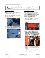
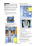
Adjust Table Chain Tension
1.
Disconnect planer from power source!!
2.
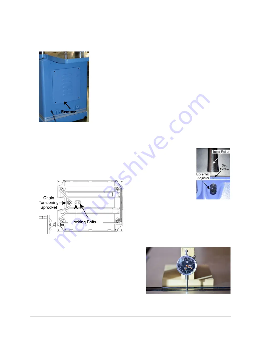
Remove motor access panel.
3.
Loosen the two locking bolts for holding the
chain tensioner bracket in place.
IMPORTANT:
Keep table chain tensioned
while loosening the locking bolt. If the chain
falls off from the sprockets, it can take a lot
of time to reinstall the chain and recalibrate
the planer.
4.
Push the chain tensioning sprocket against
the chain with moderate tension to remove
chain slack. Hold the sprocket in place, and
re-tighten the locking bolts.
5.
Clean and lubricate the chain as needed.
6.
Re-install motor access panel when
adjustments complete.
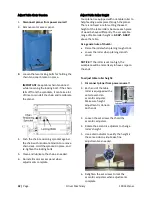
Adjust Table Roller Height
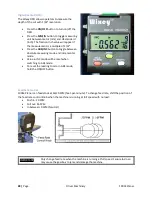
Your planer is equipped with one table roller to
help feeding a workpiece through the planer.
There is no fixed rule for setting the exact
height of the table rollers, because each piece
of wood behaves differently. The acceptable
range of table roller height is:
0.002”- 0.005”
above the table.
As a general rule of thumb:
•
Raise the roller when planing rough stock.
•
Lower the roller when planing smooth
stock.
NOTICE:
If the roller is set too high, the
workpiece will be more likely to have snipe on
the ends.
To adjust table roller height:
1.
Disconnect planer from power source!!
2.
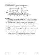
Each end of the table
roller is equipped with a
set screw and an
eccentric adjuster.
Make sure height
adjustment is done on
both ends.
3.
Loosen the set screws that hold the
eccentric adjusters.
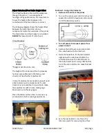
4.
Rotate the eccentric adjusters to change
roller’s height.
5.
Use a dial indicator to verify the height is
the same side-to-side. Make fine
adjustments as needed.
6.
Retighten the set screws to lock the
eccentric adjusters when adjustments
complete.
Содержание 10014
Страница 2: ......
Страница 10: ...10 Page Oliver Machinery 10014 Planer Identification...
Страница 11: ...10014 Planer OLIVERMACHINERY NET 11 Page...
Страница 12: ...12 Page Oliver Machinery 10014 Planer...
Страница 38: ...38 Page Oliver Machinery 10014 Planer Figure 1 Figure 2 Figure 3 Figure 4 Figure 5 Figure 6...
Страница 44: ...44 Page Oliver Machinery 10014 Planer between the cutterhead and the feed rollers...
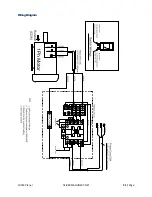
Страница 51: ...10014 Planer OLIVERMACHINERY NET 51 Page WiringDiagram...
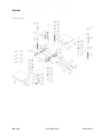
Страница 52: ...52 Page Oliver Machinery 10014 Planer PartsList Table Assembly...
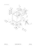
Страница 53: ...10014 Planer OLIVERMACHINERY NET 53 Page Cabinet Assembly...
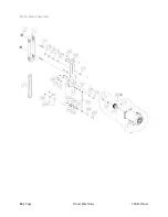
Страница 54: ...54 Page Oliver Machinery 10014 Planer Motor Mount Assembly...
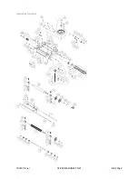
Страница 55: ...10014 Planer OLIVERMACHINERY NET 55 Page Headstock Assembly...
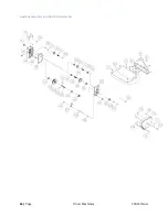
Страница 56: ...56 Page Oliver Machinery 10014 Planer Gearbox Assembly and Dust Port Assembly...
Страница 62: ...62 Page Oliver Machinery 10014 Planer MaintenanceRecord Date Task Operator...
Страница 63: ...10014 Planer OLIVERMACHINERY NET 63 Page Notes...

