40
Diagram 15
8
8..8
8..11..115
5 D
Diia
ag
grra
am
m 115
5
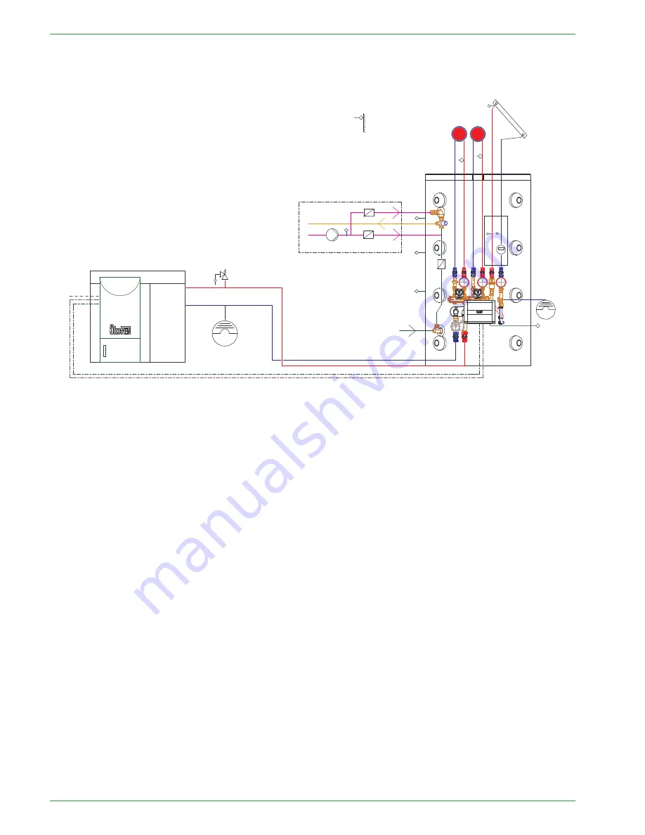
1 Boiler Pellematic – 1 Accumulator Pellaqua – Circulation on Accumulator Pellaqua – Yield Measuring Solar
1
2
Pellematic
X2
X6
X7
X8
X9
X4
X5
X15
Outdoor sensor
X29
X14
X17
X16
X19
BUS
Power
230V
Feeding - controller
* Manual
Note:
If the value on the boiler sensor from the existing boiler (X13 S2) rise above the switch temperature the pellematic will be switched off.
After reaching the adjusted pump on temperature, the diverter valve (X24), so that the energy can be taken from the existing boiler.
PE 567 EN 1.1
Содержание PE 08
Страница 16: ...16 Wiring diagrams PE 567 EN 1 1 ...
Страница 17: ...Wiring diagrams 17 Operating Manual PELLEMATIC PE S K B 10 56 ...
Страница 18: ...18 Wiring diagrams PE 567 EN 1 1 ...
Страница 76: ...76 Code Input Menu of Pelletronic Touch after entering the code PE 567 EN 1 1 ...
Страница 110: ...110 Cascade settings Back to the menu Sys Regulation PE 567 EN 1 1 ...
Страница 168: ......
Страница 169: ......


