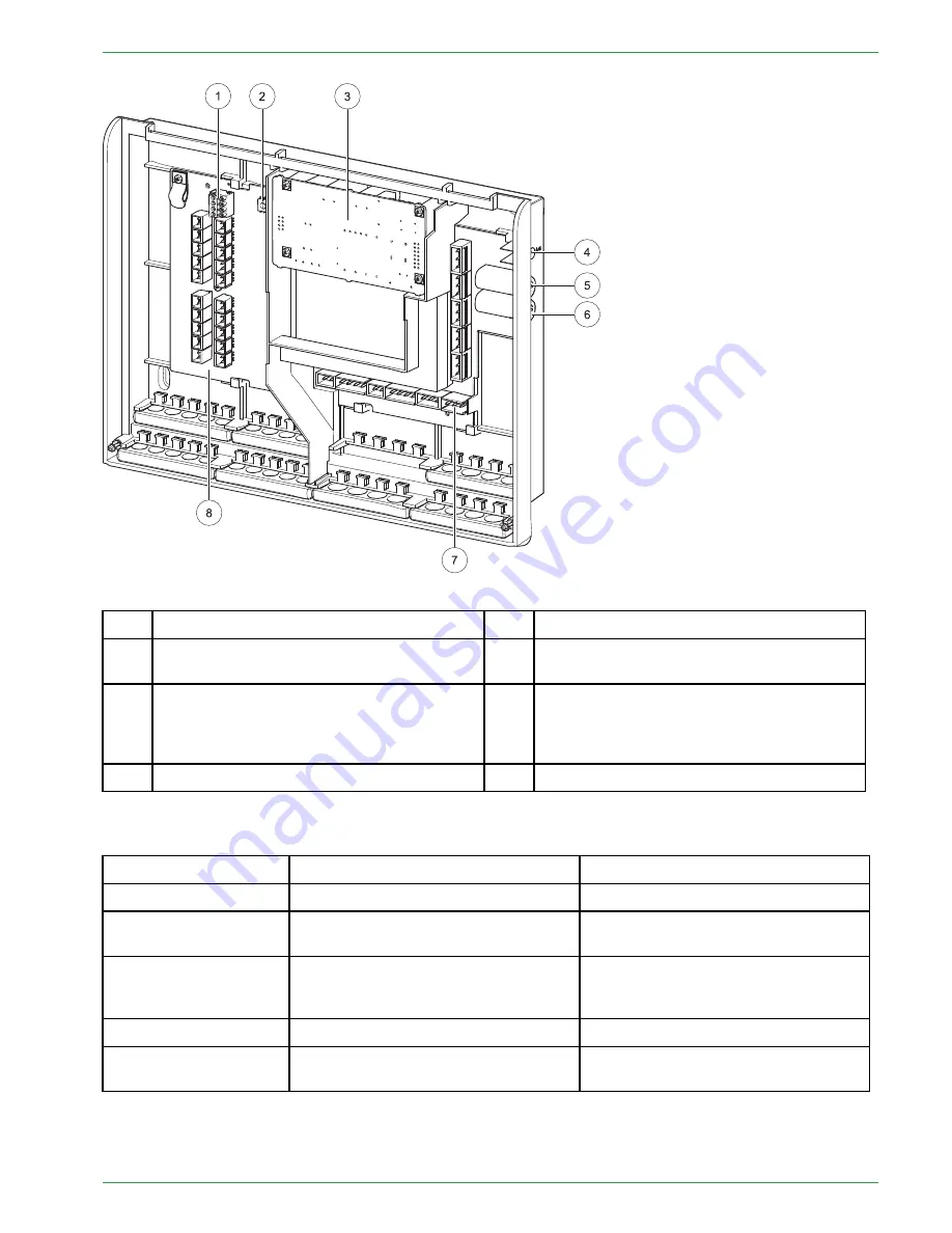
LED status heating controller
21
1
Bus connecting terminal RS485 A and B
5
Fuse 6,3 A (fast) for X31 and X33
2
Address switch
6
Fuse 8 A (slow-acting) limits the current
consumption of the heating controller.
3
Slot for an optional power supply
(The power supply is needed when the
burner control CMP 06.2 is used. The power
supply takes over the bus supply.)
7
Low voltage – area (dangerous voltage)
4
Status-LED
8
Extra low voltage (PELV)
8.1 LED status heating controller
Display
Description
Cause and remedy
red
Power supply present
—
red flashing
Error condition
no communication possible
Check software version
Check bus wiring
orange
Power supply present
Processor runs
no communication possible
Check bus wiring
green flashing
Initialization (Firmware boots)
—
green
Operation
Cyclic communication possible
—
Operating Manual PELLEMATIC® PE(S)(K)(B) 10 — 56
Содержание PE 08
Страница 16: ...16 Wiring diagrams PE 567 EN 1 1 ...
Страница 17: ...Wiring diagrams 17 Operating Manual PELLEMATIC PE S K B 10 56 ...
Страница 18: ...18 Wiring diagrams PE 567 EN 1 1 ...
Страница 76: ...76 Code Input Menu of Pelletronic Touch after entering the code PE 567 EN 1 1 ...
Страница 110: ...110 Cascade settings Back to the menu Sys Regulation PE 567 EN 1 1 ...
Страница 168: ......
Страница 169: ......


