EN-1
5000 Series Indicators
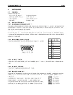
Pin
Connection
J7-1
RTS
J7-2
TXD
J7-3
RXD
J7-4
CTS
J7-5
GND
.. RS Interface Cable to T51XW
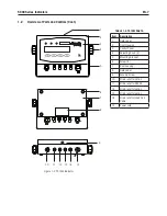
Pass the optonal RS232 cable through the stran relef (Fgure 1-2, tem 10) and attach t to
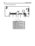
termnal block J7 (Fgure 1-3, tem 6). Tghten the stran relef to mantan a watertght seal.
.. Footswitch to T51P or T51XW
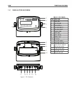
Pass the optonal footswtch cable through the stran relef (Fgure 1-1, tem 15 or Fgure 1-2, tem 11) and attach t to termnal
block J9 (Fgure 1-3, tem 5).
. T51P Rear Housing Orientation
The T51P s delvered n the wall mount orentaton wth the connectons extng below the dsplay. The rear housng may be
reversed so the connectons ext above the dsplay when the T51P s placed horzontally on a bench. To reverse the rear housng,
remove the four Phllps head screws, carefully rotate the housng 180°, and renstall the screws.
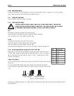
.5 Mounting Bracket
Attach the bracket to a wall or table usng fasteners (not suppled) that are approprate for the type of mountng surface. The
bracket wll accommodate up to 6 mm (1/4”) dameter screws. Locate the mountng holes as shown n Fgure 2-5.
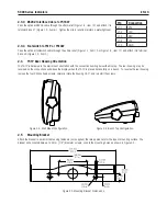
Fgure 2-3. Wall Mount Confguraton.
Fgure 2-4. Bench Top Confguraton.
Fgure 2-5 Mountng Bracket Dmensons.
Содержание T51P
Страница 1: ... 5000 Series Indicators Instruction Manual T51XW Indicator T51P Indicator ...
Страница 2: ...ii ...
Страница 63: ......


