

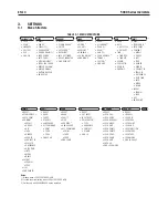


EN-1
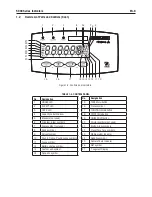
5000 Series Indicators
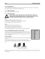
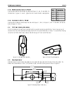
.. Mounting Bracket
Poston the wall bracket over the threaded holes n the sde of the ndcator as shown n Fgures 8-1 or 8-2 and nstall the
knobs. Adjust the ndcator to the desred angle and tghten the knobs.
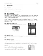
. Internal Connections
Some connectons requre the housng to be opened.
..1 Opening the Housing
CAUTION: ELECTRICAL SHOCK HAZARD. REMOVE ALL POWER CONNECTIONS TO THE INDICATOR
BEFORE SERVICING OR MAKING INTERNAL CONNECTIONS. THE HOUSING SHOULD ONLY BE OPENED
BY AUTHORIZED AND QUALIFIED PERSONNEL, SUCH AS AN ELECTRICAL TECHNICIAN.
T51P
Remove the four Phllps head screws from the rear housng.
Remove the front housng beng careful not to dsturb the nternal connectons.
Once all connectons are made, reattach the front housng.
T51XW
Remove the four hex head screws from the rear housng.
Open the housng by carefully pullng the front housng forward.
Once all connectons are made, reattach the front housng.
The screws should be tghtened to 2.5 N
•
m (20-25 n-lb) torque to ensure a watertght seal.
.. Scale Base Without Connector to T51P or T51XW
Bases wthout a connector must be attached to the nternal load cell connector on the man
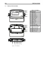
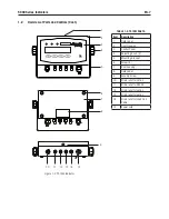
PC board. Pass the load cell cable through the stran relef (Fgure 1-1, tem 13 or Fgure 1-2,
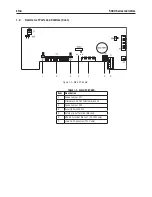
tem 13) and attach t to termnal block J4 (Fgure 1-3, tem 2). Tghten the stran relef to
mantan a watertght seal.
Pin
Connection
J4-1
+EXE
J4-2
+SEN
J4-3
+SIG
J4-4
GND
J4-5
-SIG
J4-6
-SEN
J4-7
-EXE
Jumper Connections
For a 4-wre load cell wth no sense wres: Jumpers W1 and W2 must be left n place shortng
the two pns.
For a 6-wre load cell that ncludes sense wres, Jumpers W1 and W2 must be removed.
For load cells wth an extra ground sheld wre: Connect the sheld to the center poston (GND)
of J4.
Fgure 2-2. Jumper Connectons.
After wrng s completed and jumpers are n place, replace the ndcator housng screws. Make sure the lqud-tght connector s
properly tghtened.
Содержание T51P
Страница 1: ... 5000 Series Indicators Instruction Manual T51XW Indicator T51P Indicator ...
Страница 2: ...ii ...
Страница 63: ......