

C-Nav5000 Quick Start Guide
Follow this Quick Start Guide to enable the robust functionality of
the C-Nav5000.
Your C-Nav5000 has already been tested by qualified
C-Nav Technicians. Refer to the following steps to
connect equipment and operate the receiver.
This Quick Start Guide is intended to familiarize the user with
the basic setup of the C-Nav5000 only. The supplied USB
Flash Drive (P/N CNV7CNG002-0) includes the C-Nav5000
User Guide, (
Adobe Reader required
), which contains in-depth
product information and technical specifications. Refer to the
table below for items included in the C-Nav5000 GNSS
Sensor Kit.
Table 1: Supplied Equipment
C-Nav5000 GNSS Sensor
(P/N CNV5K-PH90229916)
COM1
– LAN Ethernet Data Cable (P/N CNV5K-
PH96235870)
HDD
– 26 to USB1 device/COM2/4 Serial Cable (P/N
CNV5K-96229301)
Unterminated Ext Power/1PPS/Event with Filter (P/N
CNV5K-PH96235771)
USB Flash Drive (P/N CNV7CNG002-0)
Dual Data Adapter (P/N CNVCNV335G001-0)
110/220 VAC Power Adapter (P/N CNV5K-
PH96235770)
Harns Power Cord 2-Prong North America (P/N CNV73-
200002-00LF)
Cord, Power, IEC320-C7 (EURO) (P/N CNV4250012-
220)
Cord, Power, IEC320-C7 (UK) (P/N CNV4250013-240)
1PPS Adapter/DB9-BNC (P/N CNVCNV335G002-0)
Mounting Bracket, Top & Bottom (P/N CNV5K-
PH60229636)
Phenolic Washer Kit (P/N CNV5K-PH95232908)
Very Important
Before connecting your C-Nav5000 ensure that the
unit has been isolated using the Phenolic Washer Kit.
This hardware enables the receiver chassis to be
electrically isolated from the mounting surface.
Refer to
Section 4
– Installation
of the C-Nav5000
User Guide for detailed information.
Connect Equipment
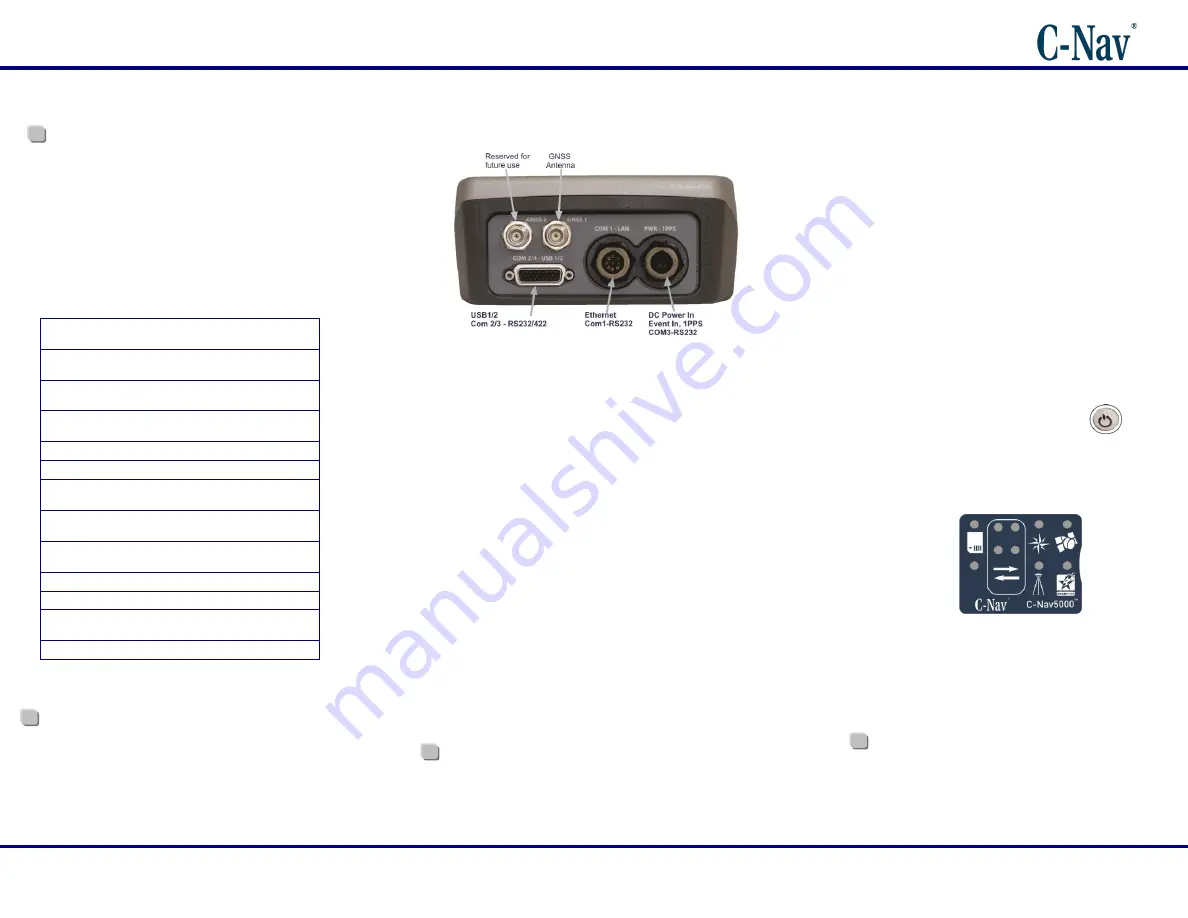
Figure 1: C-Nav5000 Rear View
Refer to
Figure 1
above for the steps below:
1.
Use one of the two supplied data cables for
communications:
Ethernet RJ45 / DB9S female Y-cable (P/N
CNV5K-PH96235870): Connect the Positronic 9-
Pin connector of the cable to COM1 - LAN at the
rear of C-Nav5000. Connect the DB9S end to the
computer or C-NaviGator CDU.
Or…
HDD
– 26 to USB1 Device/COM2/4 Serial Cable
(P/N CNV5K-96229301): Connect the 26 pin
connector of the cable to COM2/4
– USB1/2 at the
rear of C-Nav5000. Connect the DB9-1/2S end to
the computer or C-NaviGator CDU.
2.
Mount the GNSS antenna. Locate the antenna in an area
with a 360
clear view of the sky. Refer to
Section 4 -
Installation
of the C-Nav5000 User Guide for detailed
installation instructions.
3. Connect the TNC connector on one end of a C-Nav
approved GNSS antenna cable to the GNSS antenna.
Connect the other end of the cable to the TNC connector,
labeled
GNSS1
,
at the rear of the C-Nav5000.
Optional C-Nav approved Antenna Cables are available
through your authorized C-Nav Dealer, or by contacting
C-Nav Support.
4.
Perform one of these steps to setup power:
a.
If you are connecting using the optional Positronic
9-Pin Female Unterminated Power Cable (P/N
CNV5K-PH96235771), connect the power cable to
the connector labeled
PWR-1PPS
, at the rear of
the C-Nav5000. Connect the unterminated end of
the power cable to a DC power source (9 to
32VDC, 6W typical, see
Section 3
– Interfacing
of
the C-Nav5000 User Guide for power cable pin
assignments).
b.
If you are connecting using the optional AC Power
Supply Kit (P/N CNV5K-PH96235770), connect
the Positronic 9-Pin Female connector of the
Power Supply Unit to the connector labeled
PWR-
1PPS
, at the rear of the C-Nav5000. Insert an AC
Power Cord into the 2-prong receptacle on the
PSU, based on regional AC power availability
(110, 220 or 240 VAC power cords provided) and
plug into an appropriately rated wall receptacle.
5.
To power the unit ON / OFF, depress the
I/O switch
for more than 2 seconds. All front panel LEDs illuminate
for 3- 5 seconds during power-up as the receiver performs
its built-in-test. The Power / GNSS Status LED changes
to Red. Refer to
Section 3 - Interfacing
of the C-Nav5000
User Guide for LED status.
Figure 2: C-Nav5000 LED Indicator Panel
6.
Your C-Nav5000 hardware is now properly connected.
7.
At this point you may connect to C-
Nav’s C-Setup,
C-Monitor®, C-Scape or C-NaviGator controller solutions
to view real-time positioning data and to control the C-
Nav5000.
The C-Nav Corrections Service license is not a
standard feature of any Software Bundle. It is
purchased separately. Refer to reverse side of this
pamphlet for more information on obtaining a C-Nav
license.


