48
Chapter 4 How to Navigate the User Interface
Operator Interface Hardware
Operator Interface Components
[17]
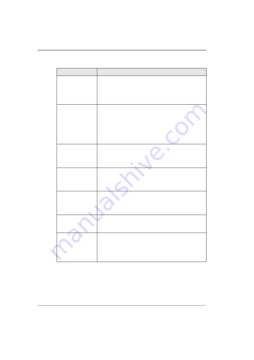
[17] Hardware Interface Components
(1 – 3)
Component
Function
1) Main Power
Switch
The Arizona 250 GT has an AC power switch that turns the
printer On and Off. The switch also serves as a lock-out
device. It also has an AC power connector. All of these
power-related items are located on the end of the electronics
enclosure.
2) Operator Control
Station
The operator control station consists of a podium stand, an
LCD display monitor, a mouse, and an emergency stop
button. The station allows the operator to control the
printer's onboard computer system by way of the Operator
Interface software displayed on the LCD monitor. Print jobs
are sent to the printer's hard drive from the host computer
over an Ethernet network.
3) Vacuum Zone
Control
The three vacuum zone control handles determine which of
the three print zones on the printer table will have vacuum
applied when the vacuum pump is switched on. The
vacuum zones are opened or closed by the handles.
4) Vacuum Table
Foot Pedal
A vacuum foot pedal switch is provided to facilitate the
process of securing the media on the vacuum table. The foot
pedal toggles the table vacuum on/off. The vacuum must be
turned on prior to starting a print.
5) Vacuum Bleed
Valve & Ga
u
ge
A bleed valve can be adjusted to reduce or increase the
amount of vacuum suction on the media. Less vacuum
reduces artifacts caused by suction when imaging on
flexible media.
6) Print Button
The print button is located at the corner where media is
loaded on the table. After positioning the media and
activating the vacuum, press the button to start the print.
7) Printer Status
Light
The green colored beacon light is mounted on the top
surface of the carriage. The purpose of the light is to
indicate basic machine status to the operator. See the table
after this section for the significance of the different states
of the light.
Содержание Arizona 250 GT
Страница 1: ...Arizona 250 GT Oc User manual User Manual Revision D...
Страница 6: ...6 Table of Contents...
Страница 7: ...7 Chapter 1 Introduction...
Страница 16: ...16 Chapter 1 Introduction Product Compliance...
Страница 17: ...17 Chapter 2 Product Overview...
Страница 21: ...21 Chapter 3 Safety Information...
Страница 45: ...45 Chapter 4 How to Navigate the User Interface...
Страница 47: ...47 Operator Interface Hardware Illustration 33 33 Vacuum System Hardware 34 34 Carriage Area Hardware...
Страница 51: ...51 Operator Interface Hardware Thermal fluid heater Purge pump Purge valve Printheads jetting...
Страница 70: ...70 Chapter 4 How to Navigate the User Interface Installation and Upgrade Module...
Страница 71: ...71 Chapter 5 How to Operate the Arizona 250 GT...
Страница 96: ...96 Chapter 5 How to Operate the Arizona 250 GT Underlay Board to Reduce Artifacts...
Страница 97: ...97 Chapter 6 How to Operate the Roll Media Option...
Страница 122: ...122 Chapter 6 How to Operate the Roll Media Option How to Determine Media Advance Correction...
Страница 123: ...123 Chapter 7 How to Use the Static Suppression Upgrade Kit...
Страница 127: ...127 Chapter 8 Ink System Management...
Страница 134: ...134 Chapter 8 Ink System Management How to Change Ink Bags...
Страница 135: ...135 Chapter 9 Error Handling and Troubleshooting...
Страница 139: ...139 Chapter 10 Printer Maintenance...
Страница 172: ...172 Chapter 10 Printer Maintenance How to Clean the Rubber Capstan...
Страница 173: ...173 Appendix A Application Information...
Страница 176: ...176 Appendix A Application Information Application Resources on the Web Site...


