

Congratulations and thank you for purchasing OBLO Li-
ving Battery Scene Controller. Below you will find useful
operating guidelines.
DEVICE DESCRIPTION
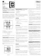
OBLO Living Battery scene controller (Illustration 1) is
wirelessly controlled electronic switch that combines
features of setting up ambiance scenes and temperature
measurement. The device is compliant with ZigBee Home
Automation (ZHA) 1.2 and is guaranteed to function with
any ZHA 1.2-compliant system. In addition, it allows pair-
ing with any device supporting ZHA binding feature.
0 - Main button,
1 - Command button 1, 2 - Command button 2,
3 - Command button 3, 4 - Command button 4,
5 - Led indicators, 6 - Battery housing
Illustration 1
OBLO Living Battery scene controller is battery operated
device (battery type CR2450).
BATTERY ACTIVATION
Battery scene controller has pre-installed battery, which
needs to be activated by gently removing the protective
film from the battery connector.
In case you need to install new battery, gently open device
housing and place the battery as shown in Illustration 2.
NOTE:
When inserting battery, make sure the polarity is
correct!
Illustration 2
MODES OF OPERATION
The device supports four modes of operation:
• Normal mode
• Scene setup mode
• Pairing mode
• Key offset mode
NOTE:
Scene setup mode, pairing mode and key offset
mode can be active only in cases when Battery scene
controller is a part of standalone network (without home
automation gateway as a central device).
Normal mode
After activation, the device enters normal mode. In this
mode the end user is able to:
• Join Battery scene controller into existing ZigBee
network
• Perform factory reset
• Change mode of operation
Scene setup mode
In this mode, the end user is able to define ambiance
scene by following next steps:
1. Press main button 5 times in order to change mode of
operation from normal to scene setup mode. During
the procedure, all LED indicators will blink green 5
times
2. All devices that will be part of the scene should be
switched to identify mode according to manufacturer’s
instructions. Set desired state on each device (e.g. light
on) for the scene
3. Press one command button on the Battery scene con-
troller in order to assign it to defined scene
4. After successful operation, all LED indicators will blink
red 5 times, which means that device switched back to
normal mode
NOTE:
When Battery scene controller is part of home au-
tomation gateway’s network, then ambiance scenes can
be defined by using gateway and client application (in ac-
cordance with manufacturer’s instructions).
Pairing mode
In this mode, the end user is able to pair Battery scene
controller with other device which supports ZHA binding
feature. This procedure is explained in a separate section
of this document.
Key offset mode
In this mode, the end user is able to change command
button’s and main button’s ID, in order to set up to 10 dif-
ferent scenes for one command button, which means that
one Battery scene controller can support up to 40 differ-
ent scenes.
Command buttons can have 40 different ID numbers
(10 per button) and main button can have 10 ID numbers
(from 0 to 9).
To set different ID numbers for one command button,
please follow next steps:
1. Press and hold main button for longer than 3 seconds
in order to change mode of operation from normal to
key offset mode. During the procedure, all LED indica-
tors will blink green 3 times
2. To operate with command button ID greater than 4, use
the formula: command button ID = 4 x (main button ID)
+ (1,2,3 or 4), e.g. if we want to operate with command
button ID 13, 14, 15 and 16 instead of 1, 2, 3 and 4 then
our desired main button ID will be 3 (initially main but-
ton ID is 0)
3. When key-offset has been set, user can operate with
appropriate com mand button ID numbers until factory
reset is performed
PREPARATION
After activating it for the first time Battery scene controller
is not associated with any ZigBee network. In order to en-
able proper functioning of the device, it has to be added to
the existing ZHA 1.2-compliant system or paired with any
device supporting ZHA binding feature.
BATTERY SCENE CONTROLLER AS A PART OF
EXISTING ZHA 1.2-COMPLIANT SYSTEM
In order to add Battery scene controller to existing ZHA
1.2-compliant system please follow next steps:
1. On the gateway’s side initiate device inclusion proce-
dure according to gateway manufacturer’s instructions
2. On the Battery scene controller press main button once
to start joining procedure. During joining procedure one
LED will blink red
3. After successful joining, LED will blink green no longer
than 3 minutes
PAIR BATTERY SCENE CONTROLLER WITH
OTHER DEVICE
In order to pair Battery scene controller with other device
supporting ZHA binding feature please follow the pro-
cedure below. Since Battery scene controller is initiator
device, the procedure assumes that pairing device has a
role of target device. For additional information about oth-
er pairing options please contact our technical support at
1. Create ZigBee network on pairing device according to
manufacturer’s instructions
2. Add Battery scene controller to pairing device’s ZigBee
network:
1) On pairing device start joining procedure accord-
ing to manufacturer’s instructions
2) On Battery scene controller press main button
once in order to start joining procedure. During the
ENG
OBLO Living
Battery Scene Controller
BC100
BSC-4ST-ZB
OBLO Living LLC
Narodnog Fronta 23a
21000 Novi Sad
Serbia
www.obloliving.com
USER MANUAL