


NXP Semiconductors
UM191812
PN544 C2 User Manual
191812
All information provided in this document is subject to legal disclaimers.
© NXP B.V. 2010. All rights reserved.
User Manual
Rev. 1.2 — 2010-06-16
8 of 172
From software point of view we refer to “PN544 HCI”. Depending on the interface used
the ETSI or the NXP proprietary one is used. For ease of nomenclature we refer to HCI
meaning NXP PN544 HCI.
HCI is used for host interfaces and UICC interface (See [1]).
The following chapters describe how to access PN544 over HCI and how to configure it.
Main parts cover the PN544 NXP HCI specifics.
6. Host hardware interface configuration
6.1 General points
The system host controller can communicate with the PN544 by using the SPI, I
2
C or
HSU (High Speed UART) serial links.
Only one link can be used at once, and the choice is done by a hardware configuration
(interface mode lines IFSEL [2:0]) during the power up sequence of the chip.
Note: The host interface check is performed by the firmware at PN544 power-up (PVDD
available) and after any Reset (Hardware or Software). See ‘Boot Sequence’ chapter of
PN544 Datasheet [7] .
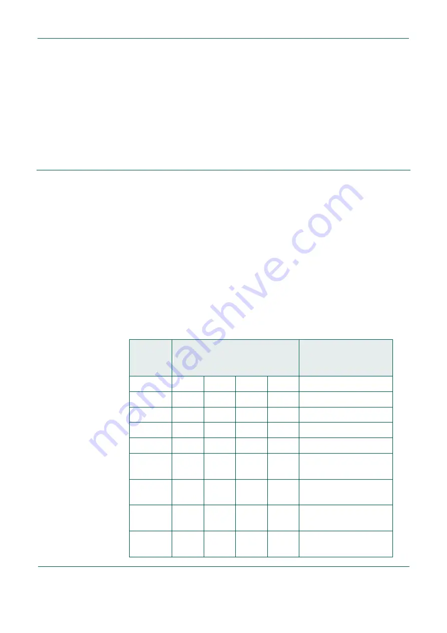
Table 2.
Host Interface Selection
Here is the description of the physical connections on pins IFSEL [2:0] (define the interface) and IF
[3:0] (physical host interface)
Interface
Selection
Pin Name
Interface Pin Name
Link
IFSEL[2:0]
IF0 IF1 IF2 IF3
000 nc
RX
nc
TX
RS232
001 - - - -
rfu
010 ADDR0
ADDR1
SDA SCL
I
2
C
011 - - - -
rfu
100
NSS MOSI SCK MISO
SPI
(CPOL=0, CPHA=0)
(1)
101
NSS MOSI SCK MISO
SPI
(CPOL=0, CPHA=1)
(1)
110
NSS MOSI SCK MISO
SPI
(CPOL=1, CPHA=0)
(1)
111
NSS MOSI SCK MISO
SPI
(CPOL=1, CPHA=1)
(1)