


NXP Semiconductors
UM11711
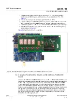
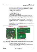
PCAL6524EV-ARD evaluation board
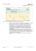
Figure 13. Graphical interface – “SWITCH” tab activated
The
LED
tab, allows the user to control the on-board user LEDs D5 to D8. (see
). In the yellow area of the window, the parameters of the I/O connected to on-
board user LEDs can be set. The parameters are:
• Value:
set the status of the on-board user LED (the logic state of the output).
• Output drive strength:
sets the drive strength of the output.
The
Write
button sets the internal registers of the DUT with the selected value in the GUI.
In the upper side of the window (the blue region) the LED1 to LED4 indicators displays
the current state of the on-board LEDs (D5 to D8).
UM11711
All information provided in this document is subject to legal disclaimers.
© NXP B.V. 2022. All rights reserved.
User manual
Rev. 1.0 — 19 January 2022
25 / 30