


NXP Semiconductors
UM11711
PCAL6524EV-ARD evaluation board
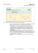
Figure 11. Graphical interface at start-up (“Settings” tab activated by default)
In the tab bar, from left to right the first tab is
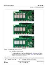
CPLD
. Clicking on
CPLD
tab, a new window
. The user can select one of three modes:
• Count mode:
when activated, three additional parameters (speed, direction and
counting status) can be set. For details regarding Count Mode and its additional
settings see
Write
button to send the configuration to the
daughterboard. The four-digit display in the upper (blue) area indicates the current
value of the physical LED display (D9 to D12) located on the PCAL6524EV-ARD
daughterboard.
• Direct Write Mode:
in this mode the user can set the value indicated by the LED
display on the PCAL6524EV-ARD daughterboard. The values “Up” and “Down” can be
chosen for LCD 1 (D9), while the other three digits can be set with numbers from 0 to 9.
The dot for each digit can be set to be on/off individually. Clicking on
Write
button the
values will be written in the daughterboard.
• Idle Mode:
In this mode the display is off, except LCD 1 (D9) which indicates the “-“
sign.
UM11711
All information provided in this document is subject to legal disclaimers.
© NXP B.V. 2022. All rights reserved.
User manual
Rev. 1.0 — 19 January 2022
23 / 30