


Universal Serial Bus Interface
MCF5253 Reference Manual, Rev. 1
24-64
Freescale Semiconductor
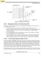
24.8.6.3
Transfer Overlay
The nine DWords in this area represent a transaction working space for the host controller. The general
operational model is that the host controller can detect whether the overlay area contains a description of
an active transfer. If it does not contain an active transfer, then it follows the Queue Head Horizontal Link
Pointer to the next queue head. The host controller will never follow the Next Transfer Queue Element or
Alternate Queue Element pointers unless it is actively attempting to advance the queue. For the duration
of the transfer, the host controller keeps the incremental status of the transfer in the overlay area. When the
transfer is complete, the results are written back to the original queue element.
The DWord3 of a Queue Head contains a pointer to the source qTD currently associated with the overlay.
The host controller uses this pointer to write back the overlay area into the source qTD after the transfer is
complete.
22–16
Hub Addr
This field is ignored by the host controller unless the EPS field indicates a full-or low-speed device.
The value is the USB device address of the USB 2.0 hub below which the full- or low-speed device
associated with this endpoint is attached. This field is used in the split-transaction protocol.
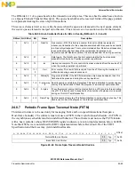
15–8 µFrame C-mask This field is ignored by the host controller unless the EPS field indicates this device is a low- or
full-speed device and this queue head is in the periodic list. This field (along with the Active and
SplitX-state fields) is used to determine during which micro-frames the host controller should execute
a complete-split transaction. When the criteria for using this field are met, a zero value in this field has
undefined behavior. This field is used by the host controller to match against the three low-order bits
of the FRINDEX register. If the FRINDEX register bits decode to a position where the µFrame C- mask
field is a one, then this queue head is a candidate for transaction execution. There may be more than
one bit in this mask set.
7–0
µFrame S-mask Interrupt Schedule Mask. This field is used for all endpoint speeds. The software should set this field
to a zero when the queue head is on the asynchronous schedule. A non-zero value in this field
indicates an interrupt endpoint. The host controller uses the value of the three low-order bits of the
FRINDEX register as an index into a bit position in this bit vector. If the µFrame S-mask field has a
one at the indexed bit position then this queue head is a candidate for transaction execution. If the
EPS field indicates the endpoint is a high-speed endpoint, then the transaction executed is
determined by the PID_Code field contained in the execution area. This field is also used to support
split transaction types: Interrupt (IN/OUT). This condition is true when this field is non-zero and the
EPS field indicates this is either a full- or low-speed device. A zero value in this field, in combination
with existing in the periodic frame list has undefined results.
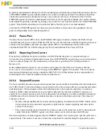
Table 24-58. Current qTD Link Pointer
Bit
Name
Description
31–5 Current qTD
Pointer
Current Element Transaction Descriptor Link Pointer. This field contains the address Of the current
transaction being processed in this queue and corresponds to memory address signals [31–5],
respectively.
4–0
–
Reserved. These bits are ignored by the host controller when using the value as an address to write data.
The actual value may vary depending on the usage.
Table 24-57. Endpoint Capabilities: Queue Head DWord 2 (continued)
Bit
Name
Description
Содержание MCF5253
Страница 1: ...Document Number MCF5253RM Rev 1 08 2008 MCF5253 Reference Manual...
Страница 26: ...MCF5253 Reference Manual Rev 1 xxvi Freescale Semiconductor...
Страница 32: ...MCF5253 Reference Manual Rev 1 xxxii Freescale Semiconductor...
Страница 46: ...MCF5253 Introduction MCF5253 Reference Manual Rev 1 1 14 Freescale Semiconductor...
Страница 62: ...Signal Description MCF5253 Reference Manual Rev 1 2 16 Freescale Semiconductor...
Страница 98: ...Instruction Cache MCF5253 Reference Manual Rev 1 5 10 Freescale Semiconductor...
Страница 104: ...Static RAM SRAM MCF5253 Reference Manual Rev 1 6 6 Freescale Semiconductor...
Страница 128: ...Synchronous DRAM Controller Module MCF5253 Reference Manual Rev 1 7 24 Freescale Semiconductor...
Страница 144: ...Bus Operation MCF5253 Reference Manual Rev 1 8 16 Freescale Semiconductor...
Страница 176: ...System Integration Module SIM MCF5253 Reference Manual Rev 1 9 32 Freescale Semiconductor...
Страница 198: ...Analog to Digital Converter ADC MCF5253 Reference Manual Rev 1 12 6 Freescale Semiconductor...
Страница 246: ...DMA Controller MCF5253 Reference Manual Rev 1 14 18 Freescale Semiconductor...
Страница 282: ...UART Modules MCF5253 Reference Manual Rev 1 15 36 Freescale Semiconductor...
Страница 298: ...Queued Serial Peripheral Interface QSPI Module MCF5253 Reference Manual Rev 1 16 16 Freescale Semiconductor...
Страница 344: ...Audio Interface Module AIM MCF5253 Reference Manual Rev 1 17 46 Freescale Semiconductor...
Страница 362: ...I2 C Modules MCF5253 Reference Manual Rev 1 18 18 Freescale Semiconductor...
Страница 370: ...Boot ROM MCF5253 Reference Manual Rev 1 19 8 Freescale Semiconductor...


