NXP Semiconductors LPCxpresso55S28 Скачать руководство пользователя страница 18

UM11158

All information provided in this document is subject to legal disclaimers.

© NXP B.V. 2022. All rights reserved.

User manual

Rev. 1.6 — 17 March 2022 

18 of 24


NXP Semiconductors

UM11158

LPCXpresso55S69/55S28 Development Boards

Note that jumper J10 may also be used as a convenient way to always assert ISP when 
the LPC55Sxx is reset or powered up. This jumper is in parallel with S1.

7.5.2 User (S3) and Wake (S2) buttons

The User (S3) and Wake (S2) buttons are intended for user application use. These 
buttons pull ports P1_9 (User) and P1_18 (Wake) low when the button is pressed. 
100kohm resistors are used to pull these two ports to VDD then the buttons are not 
pressed.

7.5.3 Reset

Pressing this button will assert reset to the LPC55Sxx and to the Mikroe and Arduino 
connector sites. Note that the Debug Probe (LPC4322) is not reset when this button is 
pressed.

7.6 Crystals

For applications requiring high-speed communication such as high-speed USB and
accurate clock such as real-time clock (RTC), two external crystals are provided on the 
board, 16MHz crystal for XTAL32M and 32.768KHz for XTAL32K.

External capacitors are not required on the crystal pins, but are installed on Revision A1 
and A2 boards. These may be removed for better performance if issues are observed. 
See the “Chapter 12: LPC55S6x/LPC55S2x/LPC552x Cap Bank API” of the 
LPC55S6x/LPC55S2x/LPC552x User manual for further information.

8. Expansion 

connectors

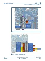
The LPCXpresso55S69 includes 3 expansion connector sets, incorporating support for 
Arduino UNO R3, Mikroe Click and PMod standards. The Arduino UNO connector 
footprint is surrounded by additional connectors that are compatible with other 
LPCXpresso V3 boards. Pin out diagrams are provided below in 

Figure 4

 and 

Figure 5

For further details, refer to the board schematics.

8.1  Mikroe Click Site

The connectors P23 and P24 provide a Mikroe Click module site for the wide range of
add-on modules available from MikroElektronika. Note that this site shares the same SPI, 
I2C and UART connections as the Arduino/LPCXpresso V3 expansion connectors.

8.2  Host / PMod Connector

Connector P20 is a optional connector (not installed by default) which can provide
convenient access for a remote host to the SPI and I2C ports of the LPC55Sxx that
support ISP mode. When setting up the Board to be used with a host, jumper P1 must be
installed to prevent conflict with the Link2 (which can also emulate an SPI or I2C host).
Jumper J4 can be used to force the LPC55Sxx to boot in ISP mode, and connector P14

can be installed and used to provide an external reset control input from the host, The 
connector footprint and connection can also be used to connect to external PMod 
peripherals that follow the PMod I2C, or SPI (Type 2 or 2A) standards. Refer to the PMod 
specifications from Digilent Inc. for more information.

Содержание LPCxpresso55S28

Страница 1: ...28 Development Boards Rev 1 6 17 March 2022 User manual Document information Info Content Keywords LPC55S69 LPC55S6x LPCXpresso55S69 LPC55S69 EVK LPC55S28 LPCXpresso55S28 LPC55S28 EVK Abstract LPCXpre...

Страница 2: ...t labeling of external serial connector Renamed section 10 to Errata added information about regulator errata Revision A2 boards 1 4 20191114 Added information about tool version requirements 1 3 2019...

Страница 3: ...t platforms for the LPC55S6x and LPC55S2x LPC552x families of MCUs respectively See https www nxp com demoboard LPC55S69 EVK or https www nxp com demoboard LPC55S69 EVK for more information on these b...

Страница 4: ...Link protocol options UART and SPI port bridging from LPC55Sxx target to USB via the onboard debug probe Optional external debug probes with trace option 10 or 20 pin Cortex M connectors RGB user LED...

Страница 5: ...4 NXP Semiconductors UM11158 LPCXpresso55S69 55S28 Development Boards 2 Board layout and Settings Figure 2 shows the layout of the board top side indicating location of the connectors and buttons whil...

Страница 6: ...ion 7 1 J3 Buffer Power Selection For On board Target place in position 1 2 default For Off board Target place in position 2 3 1 2 Section 3 2 Section 4 4 J4 Link2 LPC43xx force DFU boot Leave this ju...

Страница 7: ...e Vbus i e enable USB host capability Installed USB1 Section 6 1 J10 ISP boot jumper for LPC55Sxx Installing this jumper ties port P0_5 to ground forcing the LPC55Sxx into ISP mode whenever it is rese...

Страница 8: ...negative voltage references for the LPC55Sxx ADC An external positive reference may be connected to pin 1 Note that a solder jumper zero ohm resistor must be in position 2 3 on J8 An external negative...

Страница 9: ...f these companies for further information 3 1 Tool version requirements To ensure correct debugger operation the following tool versions are recommended IAR Embedded Workbench EWARM version 8 40 2 or...

Страница 10: ...tual COM port and Debug Probe features will not be available if the board is not first initialized by the MCUXpresso IDE 3 2 1 Installation steps for use with MCUXpresso IDE Download and install the M...

Страница 11: ...ed demo Allow about 30 seconds for the Link2 devices to enumerate for the first time It is not necessary to check the Hardware Manager on your host computer however if this is done there will be five...

Страница 12: ...to a host computer for example the VCOM port can be used if the board is running an application when no debugger is running In order to correctly install and use the Link2 device on the LPCXpresso55S6...

Страница 13: ...ate with a unique identifier On Windows to determine the COM port open the Windows operating system Device Manager This can be achieved by going to the Windows operating system Start menu and typing D...

Страница 14: ...n require a minimum supply voltage of 1 85V so jumper P4 must be set in the 3 3V position or an external supply provided to the center pin of P4 For Revision A2 boards P4 may be set in the 1 8V positi...

Страница 15: ...onnect power from a load switch to the VBUS signal of the port selected J6 should be placed in position 1 2 for USB1 or position 2 3 for USB0 If neither USB port is being used as a USB host this jumpe...

Страница 16: ...c The board design assumes pad sharing between Flexcom 6 and Flexcom 7 for I2S connections I2S connections from the LPC55Sxx are also connected to the Expansion connectors solder jumpers may be remove...

Страница 17: ...ntrolled by LPC55Sxx ports P1_4 Blue P1_6 Red P1_7 Green with the LEDs being illuminated when the respective LED is pulled low Note that these port lines are also connected to expansion connector P18...

Страница 18: ...552x Cap Bank API of the LPC55S6x LPC55S2x LPC552x User manual for further information 8 Expansion connectors The LPCXpresso55S69 includes 3 expansion connector sets incorporating support for Arduino...

Страница 19: ...rt Notes SDIO Clock P0_7 IOCON function 2 SDIO Command P0_8 IOCON function 2 D0 P0_9 IOCON function 2 D1 P0_17 IOCON function 2 D2 P0_24 IOCON function 2 D3 P0_25 IOCON function 2 Card detect P0_21 IO...

Страница 20: ...is subject to legal disclaimers NXP B V 2022 All rights reserved User manual Rev 1 6 17 March 2022 20 of 24 NXP Semiconductors UM11158 LPCXpresso55S69 55S28 Development Boards Fig 4 P16 and P19 conne...

Страница 21: ...ted to PIO0_16 and PIO0_23 10 Errata 10 1 Brown out detect BOD may be triggered during boot code execution from ROM Initial production LPCXpresso55S69 boards marked as Revision A1 use LPC55S69 revisio...

Страница 22: ...rise time of the power supply on the LPC55S69 S28 does not meet the power up ramp conditions specified in the datasheet Please see the data sheet and VBAT_DCDC 1 errata in the errata sheet 11 Board o...

Страница 23: ...ng the Link2 firmware 13 4 3 VCOM port 13 4 4 Configuring the LPCXpresso55S69 to debug an off board target 13 5 Board Power 14 5 1 1 8V operation 14 5 2 Measuring LPC55Sxx device supply current 15 6 B...

Страница 24: ...ducts for use in customer s applications NXP accepts no liability for any vulnerability Customer should regularly check security updates from NXP and follow up appropriately Customer shall select prod...

Страница 25: ...marks of Mobileye Vision Technologies Ltd in the United States the EU and or other jurisdictions NXP B V 2018 2022 All rights reserved For more information please visit http www nxp com For sales offi...

Отзывы: