


UM10503
All information provided in this document is subject to legal disclaimers.
© NXP B.V. 2015. All rights reserved.
User manual
Rev. 2.1 — 10 December 2015
61 of 1441
NXP Semiconductors
UM10503
Chapter 5: LPC43xx Boot ROM
5.3.4.2 EMC boot modes
The EMC boot process follows the main flow shown in
. The CPU clock is set to
96 MHz, and a non-AES capable part will boot directly from EMC when the image does
not contain a header. EMC uses 0xE wait states providing approximately 156 ns delay
before capturing data.
Note that the number of address bits selected in pin configuration is initially EMC_A[13:0].
All higher address bit pins are configured as pull down but not actively driven. After
reading the header, the address bits are extended to be in line with the image size as
defined by HASH_SIZE, e.g. if HASH_SIZE is 100 kB then pins EMC_A[16:14] are
configured since 2
17
> 100 kB. When booting without header, then the image should
configure extra address pins if more are needed beyond the initially configured
EMC_A[13:0]. This configuration should happen in the initial 16 kB area of the image.
If no header is present it is assumed that the image is located at address 0x1C00 0000
and is executed from there.
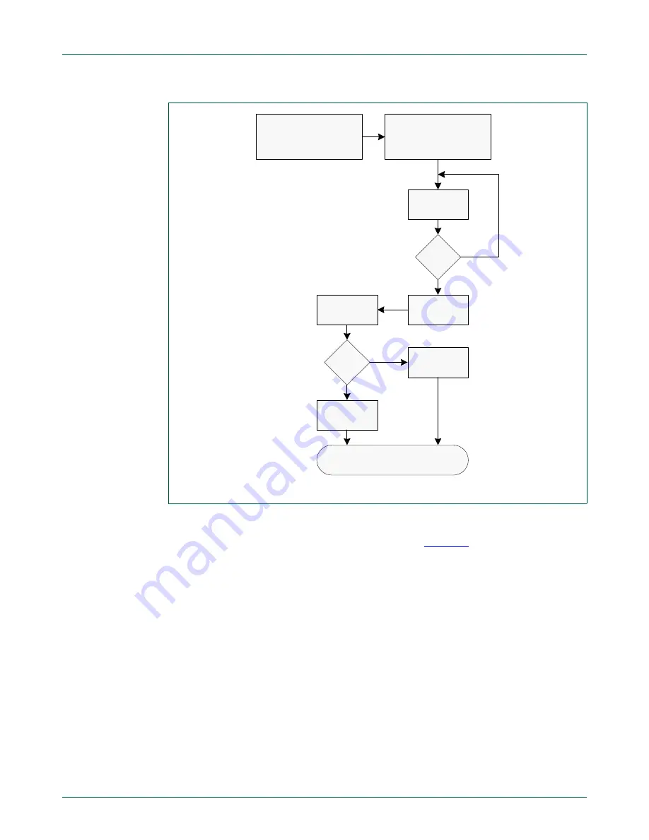
Fig 17. UART boot process
Init UART assuming
PCLK =12MHz
Setup Pin
Configuration
UART0 P2_1, P2_0 or
UART3 P2_3,P2_4
see main boot flow
char
= 0x3F?
receive
character
no
transmit
“OK” CR
LF
yes
receive
image
valid
image?
transmit
“OK” CR
LF
yes
transmit
“FAILED”
CR LF
no


