background image


nVent.com

  |

  16 


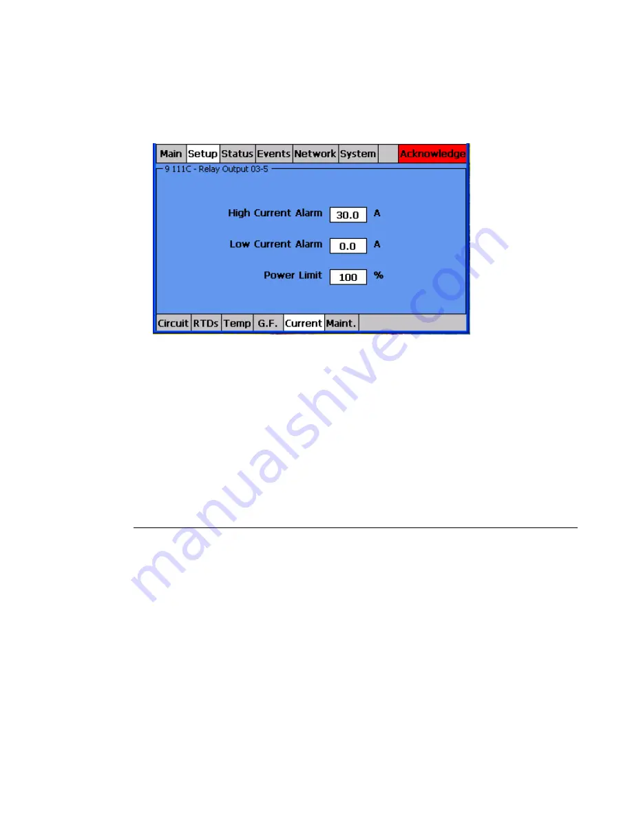
“The current monitoring set points and alarm thresholds are set in the Current menu.” 


The user usually goes to the Current menu and may begin making changes. 


I usually only point out that this is where the data is entered for current and then 

move on. 


Figure 9: Setting Line Current Values 

 
“Now let’s return to the Main screen. That’s all there is to setting up a circuit.” 


I usually point out how little direction was given to the person running the NGC-30 

UIT, that entries were fairly intuitive and just by looking at the screens that person 

could figure out what they were supposed to do. 


Make the point that this is one of the most valuable things about the NGC-30 

systems – it is an intuitive interface that uses plain language and is easy for users 

to figure out. 


Alarms and the Events Lists 

This section shows the group how the NGC-30 notifies the user of alarm conditions and how 

to use the Events list to see active or specific alarms. 


Instruct the user to go to push the red Ground-Fault Trip button on the left side of 

the demo unit. 


The red Circuit power indicator light should go off and the red “Aknowledge” fault 

indication section of the UIT screen should illuminate. 

“What we just did was to induce a ground current fault in circuit 1. The NGC-30 system 

responds by first disabling the circuit and then posting the red fault indicator with the word 

“Aknowledge” in it. The UIT display also changes the circuit #1 text to red to provide a visual 

indication that this is where the problem is.” 
“Touching the fault indicator area will bring you to the Events screen where this fault is 

displayed in flashing red. It is displayed in flashing red because it is considered an operator 

safety related fault. This means that if the fault goes away, the circuit does not 

automatically turn on, it must be manually reset.” 

Содержание NGC-30

Страница 1: ...nVent com 1 NGC 30 LUNCH AND LEARN MANUAL ...

Страница 2: ...tion Charts 4 RTD Switch Settings 4 Color Coding of Main Screen 4 nVent RAYCHEM NGC 30 CRM CRMS LED Functions 4 Getting Started 5 Demonstration Flow 5 Set the Stage 6 The Main Screen 8 Get Someone Involved 9 Program a Circuit 10 Alarms and the Events Lists 16 The Network Tab 17 Security 19 ...

Страница 3: ...ion Diagram Connecting to the Demo Unit See the nVent RAYCHEM NGC 30 Demo Unit Connection Guide for instructions on how to connect your computer to the NGC 30 Demo Unit and run the CER Host Program and RAYCHEM Supervisor ...

Страница 4: ... D 183ºF 84ºC E Shorted E Shorted F Open F Open Color Coding of Main Screen The data in the F C Amps and G F columns are displayed in color to identify their current state Color Description Green When heater is energized status On within Normal range of setup parameters Red In Alarm condition Orange F C only Temperature not within setpoint Dead Band range NGC 30 CRM CRMS LED Functions ...

Страница 5: ...e demo unit Program a Circuit The idea here is to provide as little guidance as possible and let the person figure it out in real time This shows the audience how easy the UIT makes interacting with the system Show an Alarm and the Events List Features This allows us to emphasize the alarm notification features and that everything is in plain language not secret codes The Network Tab It demonstrat...

Страница 6: ...and that each UIT in the field supports each of these o RS 232 for at the panel interface if you re using nVent RAYCHEM Supervisor on a laptop o RS 485 the main communications interface between the control boards the UIT and accessories like the nVent RAYCHEM RMM2 and PLI Demonstration panel these are the adjustment knobs and are used to show the system response to changes in temperature line curr...

Страница 7: ...nVent com 7 CRMS Control Board Touch Screen Demonstration Panel ...

Страница 8: ...s screen will appear with additional information o Then touch the Main tab to return to the Main screen Setpoint is listed so that you can compare the measured temperature to the setpoint Because no one knows what the target temperature is from memory For circuits with On Off control mode the deadband setting is displayed Then the line current and ground fault currents are displayed The status of ...

Страница 9: ...ested in new cool technology like this Their boss if attending will usually pressure them go up They re the ones who will talk about this to their peers if we make a good impression Regardless you need to get someone to run the touch screen instead of you The touch screen interface is a primary differentiator for us and you need to have the audience walk away feeling like they could figure it out ...

Страница 10: ...asking them to Program a circuit ask them How would you set up a circuit What do you think you would do This guides them towards touching the Setup tab at the top of the screen Step 1 The demo unit should have the Main screen on display If not instruct the user on how to get there Touch the Main tab Figure 2 The Setup Screen Preface the activity with a version of the following script The NGC syste...

Страница 11: ... pop up box If the user is touching the word Circuit instead of the white box then address the whole group and say Any time that you want to make an entry touching the white boxes gets you to that information entry point If circuit 5 already exists have the user select another number Figure 3 Entering the Circuit Number Next we want to create a label or ID for that circuit How would you do that Pi...

Страница 12: ...r and at least one relay should be unassigned User should select one of the unassigned relays At that point the ID text will automatically be dropped into the unassigned box that was selected and all that has to be done to complete this is for the user to touch the Next button If all the relays are assigned simply instruct the user to Cancel out of the Assign Relay Number screen select a circuit n...

Страница 13: ... should touch the white box next to the word Mode Advise the user to select On Off mode for simplicity Figure 6 Select a Control Mode Now RTD s must be assigned to this circuit Give the user some time to figure out how to get to the RTD screens before you direct them to the bottom menu tabs ...

Страница 14: ...ave the user enter one of the device addresses in the device box The user should now enter an RTD Number for the corresponding device address o If for either the device address or the RTD Number the user enters a number and that number doesn t get displayed on screen it is probably the case that the user has entered an incorrect number This is one of the idiot proofing features of the C M system A...

Страница 15: ... for an alarm and one for trip We added the alarm to give operators and indication that a ground fault problem may be coming so that they can put it on their schedule to investigate Without this feature the control system would just shut down the heat tracing when the trip threshold was reached and now repair becomes critical The Alarm feature helps manage these issues if they occur without having...

Страница 16: ...ection shows the group how the NGC 30 notifies the user of alarm conditions and how to use the Events list to see active or specific alarms Instruct the user to go to push the red Ground Fault Trip button on the left side of the demo unit The red Circuit power indicator light should go off and the red Aknowledge fault indication section of the UIT screen should illuminate What we just did was to i...

Страница 17: ...full list of 2 000 events to see what you want The Events list can also be downloaded either to a USB stick or via RAYCHEM Supervisor so you can keep a history or archive if you like Figure 10 The Events Screen The Network Tab The Network tab is a great asset when commissioning a system because it allows the heat tracing documentation to be compared directly to how the NGC 30 system thinks it is s...

Страница 18: ...t the NGC UIT sees are listed If you know that you are supposed to have all of the RTD s from 1 to 8 but you look at the list and 4 is missing then you know you have a wiring problem So before you even begin looking at faults you are confident that at least all the devices are there This is very powerful in reducing the time it takes to commission the system Figure 11 The Network Screen Going to t...

Страница 19: ... alarms that are generated when the panel is first turned on This is powerful useful stuff which no one else on the market has today Security This section addresses the security features of the NGC 30 System The NGC 30 system incorporates two levels of passwords to protect the settings from unauthorized change Instruct the user to go to the System Password tab and press Yes or OK But caution them ...

Страница 20: ...t I ask if there are any questions as an hour has usually passed and the meeting will begin breaking up Anything you get asked that you don t know the answer to write down and call product marketing Feel free to try us via cell phone during the meeting if you want ...

Страница 21: ...688 Fax 86 21 5426 3167 cn thermal info nvent com Latin America Tel 1 713 868 4800 Fax 1 713 868 2333 thermal info nvent com 2018 nVent All nVent marks and logos are owned or licensed by nVent Services GmbH or its affiliates All other trademarks are the property of their respective owners nVent reserves the right to change specifications without notice Raychem AR H58451 NGC30Learn EN 1806 21 nVent...

Отзывы: