


M0A21/M0A23 Series
May 06, 2022
Page
688
of 746
Rev 1.02
M0
A21
/M
0
A
2
3
SE
RIES
TEC
H
NICAL
RE
FEREN
C
E
M
ANUAL
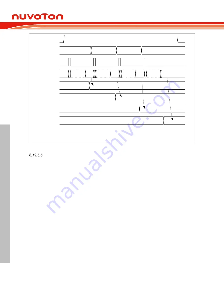
ADST
SAMPLE
A/D converter
channel select
0x0
0x2
0x3
0x7
ADDR0
ADDR2
ADDR3
ADDR7
Single-cycle scan on channel 0, 2, 3 and 7
ADC analog
macro output
R0
R0
R2
R3
R7
R2
R3
R7
Note: SAMPLE is an internal signal indicates sample stage
Figure 6.19-5 Single-Cycle Scan Mode on Enabled Channels Timing Diagram
Continuous Scan Mode
In Continuous Scan mode, A/D conversion is performed sequentially on the specified channels that
enabled by CHEN bits in ADC_ADCHER register (maximum 21 channels for ADC). The operations are
as follows:
1. When the ADST bit in ADC_ADCR register is set to 1 by software or external trigger input, A/D
conversion is started on the enabled channel with the smallest number.
2. When A/D conversion for each enabled channel is completed, the result of each enabled
channel is stored in the ADC data register corresponding to each enabled channel.
3. When A/D converter completes the conversions of all enabled channels sequentially, the ADF
bit in ADC_ADSR0 register will be set to 1. If the ADC interrupt function is enabled, the ADC
interrupt occurs. The conversion of the enabled channel with the smallest number will start
again if software does not clear the ADST bit.
4. As long as the ADST bit remains at 1, the step 2 ~ 3 will be repeated. When ADST is cleared
to 0, ADC cannot finish the current conversion and A/D converter enters idle state directly.
An example timing diagram for Continuous Scan mode on enabled channels (0, 2, 3 and 7) is shown
below.


