


NUC126
Aug. 08, 2018
Page
423
of 943
Rev 1.03
NUC12
6 S
E
RI
E
S
T
E
CH
NI
CA
L R
E
F
E
RE
NCE
MA
NUA
L
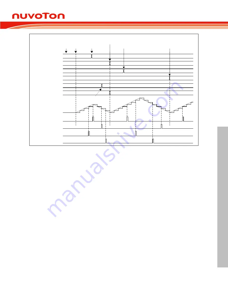
CMPDAT
PERIOD
S/W Write PERIOD
CNT
4
7
3
start
Initialize
PWM
2
S/W Write CMPDAT
0
1
2
3
4
3
1
2
0
1
2
3
4
3
1
2
0
5
6
7
6
4
5
1
2
3
4
Load from PERIOD to PBUF,
from FTCMPDAT to FTCMPBUF
Load from CMPDAT
to CMPBUF
PBUF
4
7
CMPBUF
3
2
FTCMPDAT
2
5
FTCMPBUF
2
5
S/W Write
FTCMPDAT
CMPU
CMPD
FTCMPU
FTCMPD
Figure 6.13-11 PWM Double Buffering Illustration
6.13.5.8 Period Loading Mode
When immediately loading mode, window loading mode and center loading mode are disabled that
IMMLDENn bits, WINLDENn bits and CTRLDn bits of PWM_CTL0 register are set to 0, PWM operates
at period Loading mode. In period Loading mode, CLKPSC(PWM_CLKPSCn_m[11:0]),
PERIOD(PWM_PERIODn[15:0]) and CMP(PWM_CMPDATn[15:0]) will all load to their active
CPSCBUF, PBUF and CMPBUF registers while each period is completed. For example, after PWM
counter up counts from zero to PERIOD in the up-counter operation or down counts from PERIOD to
zero in the down-counter operation or up counts from zero to PERIOD and then down counts to zero in
the up-down counter operation.
Figure 6.13-12 shows period loading timing of up-count operation, where PERIOD DATA0 denotes the
initial data of PERIOD, PERIOD DATA1 denotes the first updated PERIOD data by software and so
on. CMPDAT also follows this rule. The following describes steps sequence of Figure 6.13-12. User
can know the PERIOD and CMPDAT update condition, by watching PWM period and CMPU event.
1. Software writes CMPDAT DATA1 to CMPDAT at point 1.
2. Hardware loads CMPDAT DATA1 to CMPBUF at the end of PWM period at point 2.
3. Software writes PERIOD DATA1 to PERIOD at point 3.
4. Hardware loads PERIOD DATA1 to PBUF at the end of PWM period at point 4.
5. Software writes PERIOD DATA2 to PERIOD at point 5.
6. Hardware loads PERIOD DATA2 to PBUF at the end of PWM period at point 6.