
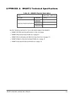


APPENDIX A SMART2 Technical Specifications
SMART2 Installation and Operation Manual 1
72
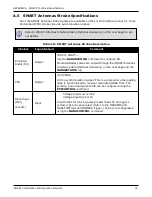
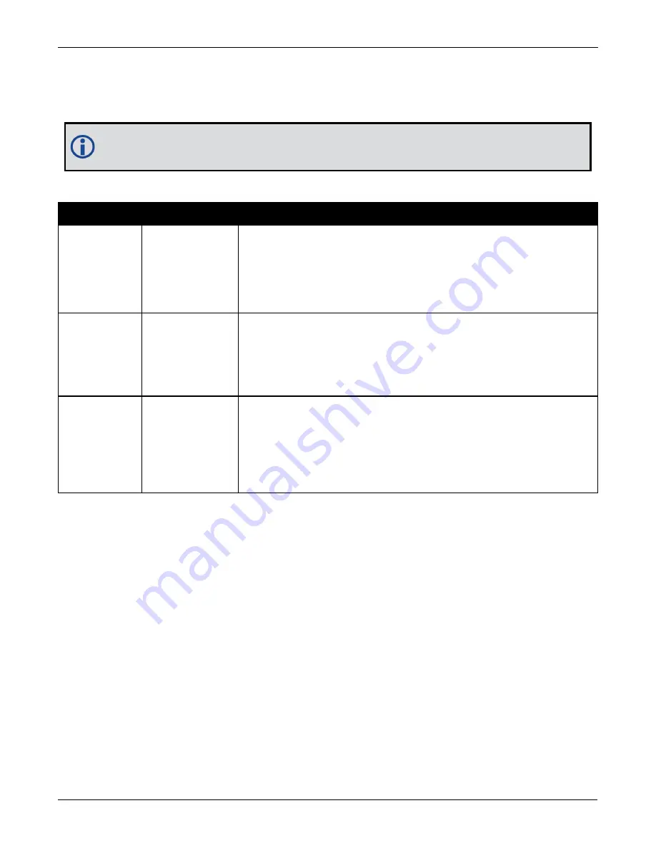
A.5 SMART Antennas Strobe Specifications
All of the SMART Antenna strobe signals are available on the 14-Pin Interface connector. Pulse
Per Second (PPS) strobes provide synchronization signal.
Refer to
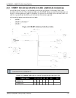
SMART Antennas Interface Cable (Optional Accessory)
on the next page for pin
out details.
Strobes
Input/Output
Comment
Emulated
Radar (ER)
Output
0VDC to VBATT+
Use the
RADARCONFIG
command to configure ER.
Emulated Radar pulses are output through the
Interface Cable (Optional Accessory)
on the next page and the
RADARSTATUS
log.
PPS
Output
3.3V CMOS
A time synchronization output. This is a pulse where the leading
edge is synchronized to receiver calculated GNSS Time. The
polarity, period and pulse width can be configured using the
PPSCONTROL
command.
Mark Input
(MKI)
(Event1)
Input
Voltage Input Low is 0.8V
Voltage Input High is 2V
Input marks for which a pulse greater than 150 ns triggers
certain logs to be generated. (Refer to the MARKPOS and
MARKTIME logs and ONMARK trigger.) Polarity is configurable
using the
MARKCONTROL
command.
Table 18: SMART Antennas Strobes Description